Introduction
In recent years, new energy vehicles have made great progress in major mainstream automobile markets around the world. According to data from the European Automobile Manufacturers Association ACEA, the cumulative registration volume of new energy vehicles (BEV+ PHEV ) in EU countries from January to October 2023 was about 1.94 million. units, a year-on-year increase of about 32%, and a penetration rate of more than 20%; according to the data released by the China Passenger Car Association , China's new energy vehicle retail sales in the same period reached 5.962 million units, a year-on-year increase of 34.7%, and a penetration rate of 34.5%.
With the expansion of the market and the maturity of the relevant industrial chain, new energy vehicles have long since changed from being policy-driven to being product-driven. From the new energy electric vehicle products in recent years, we can also see that there have been great improvements in terms of autonomous driving, intelligent cockpit, cruising range, and electric drive system performance.
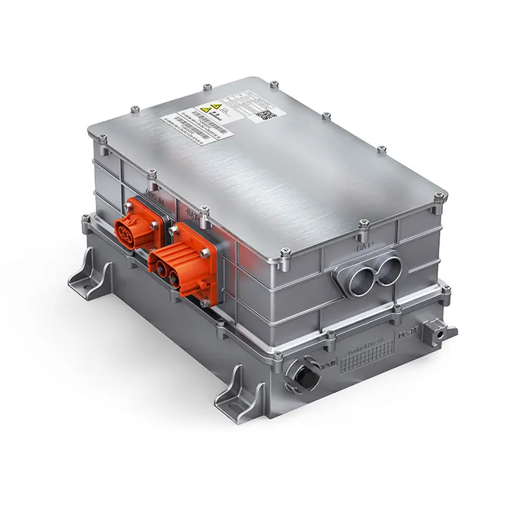
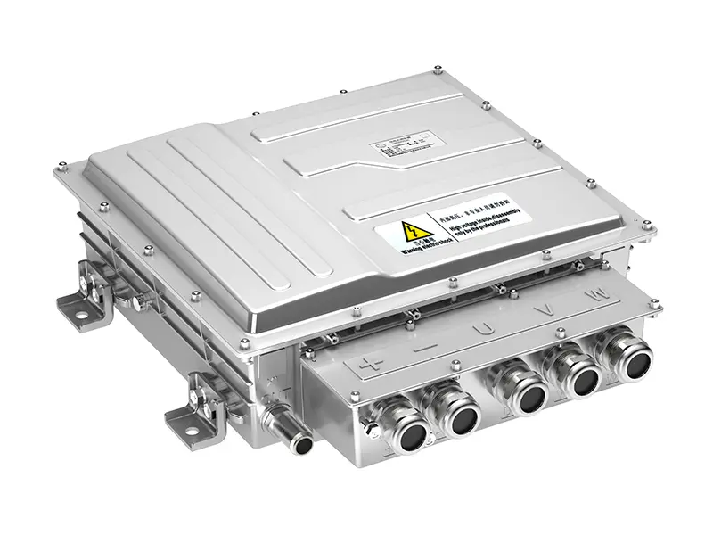
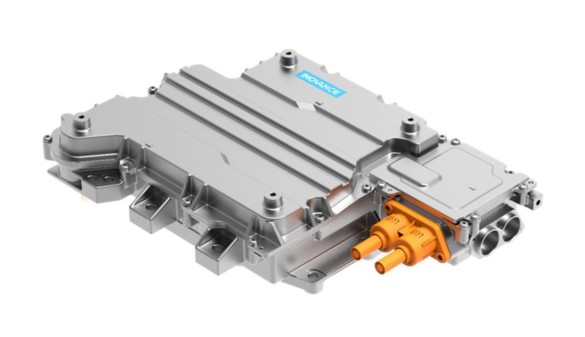
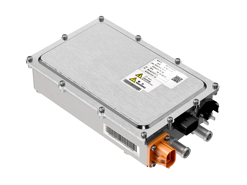
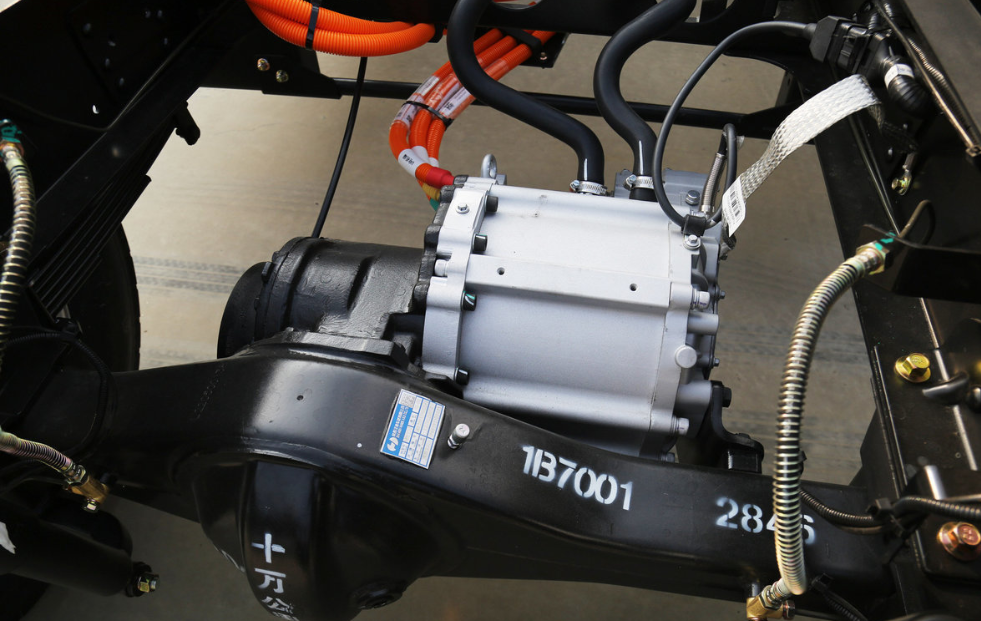
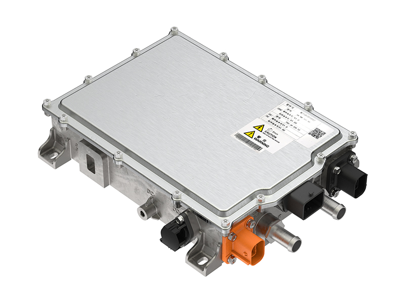
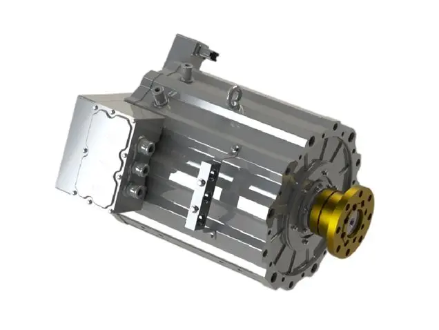
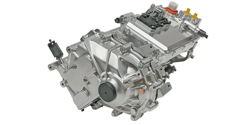
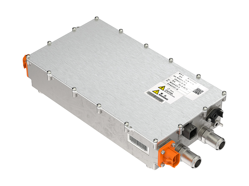
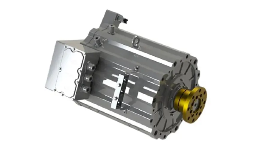
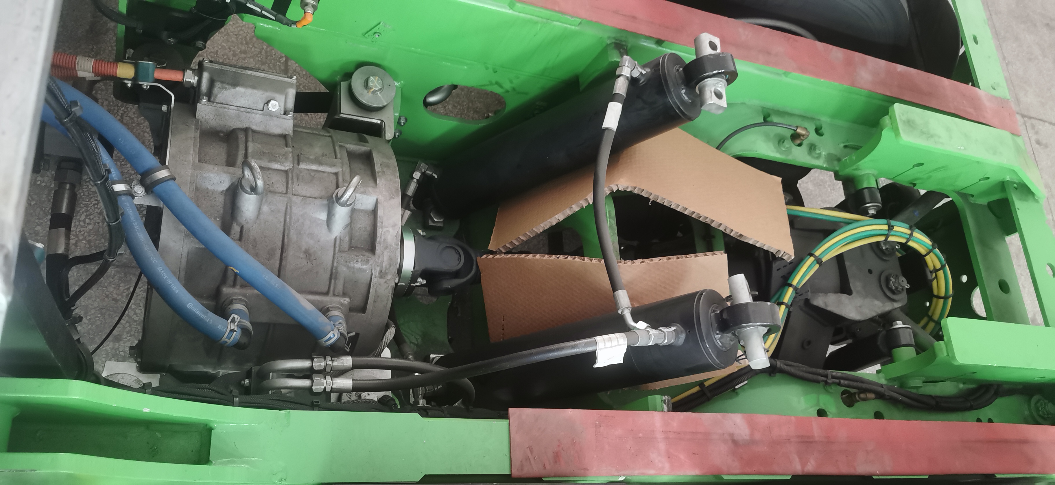
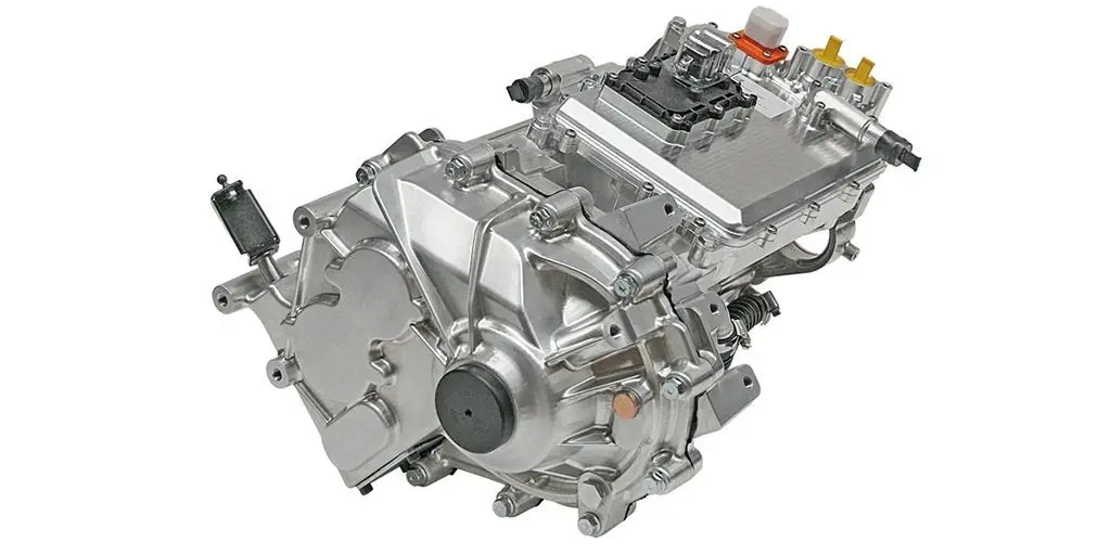
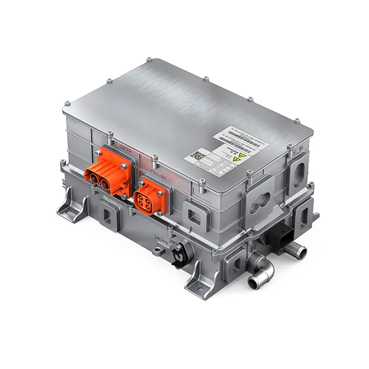
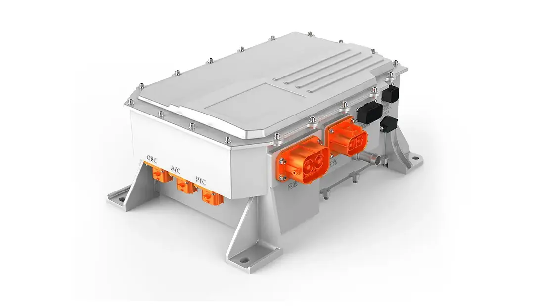
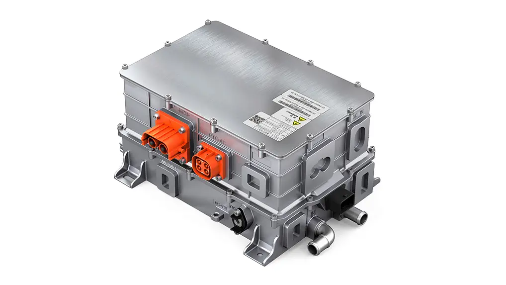
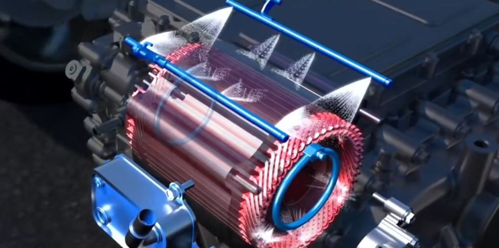
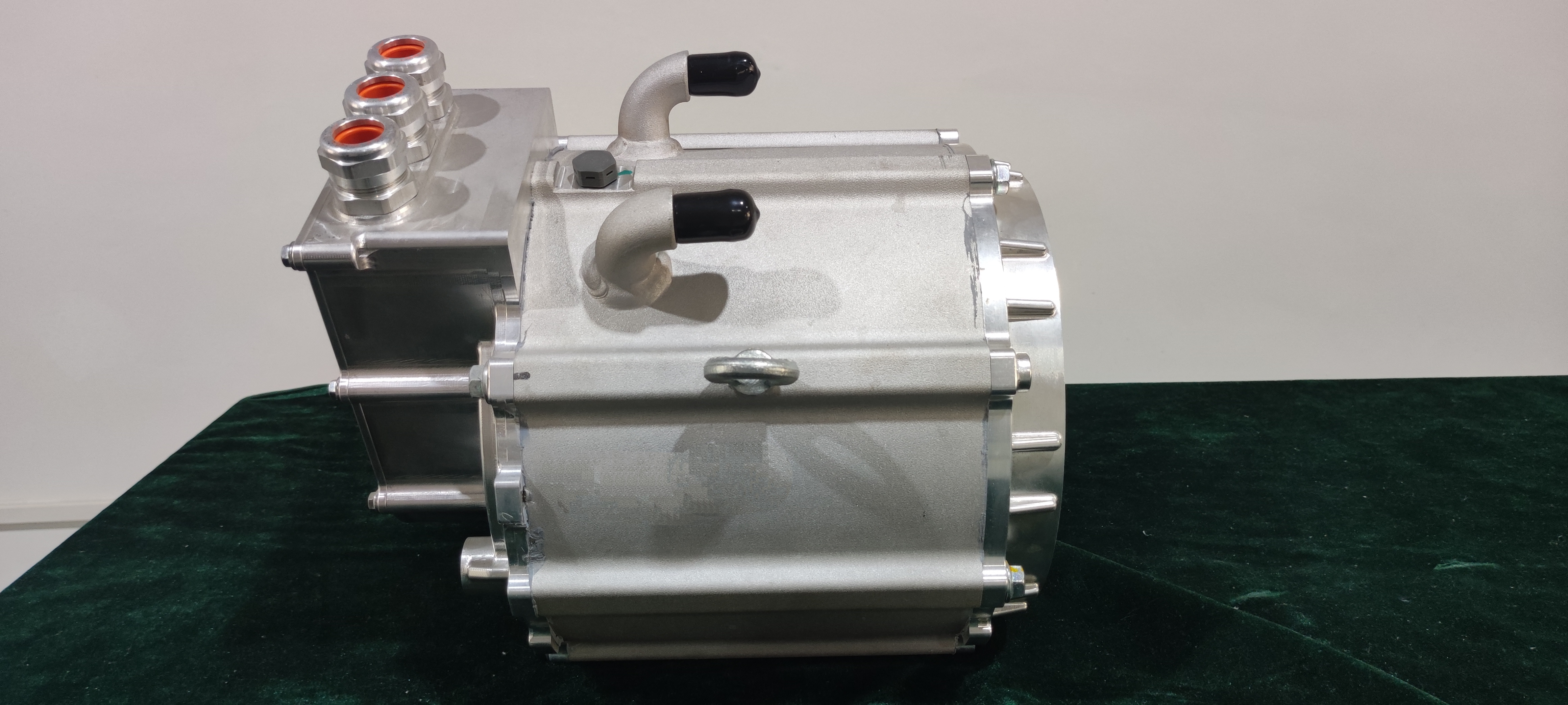
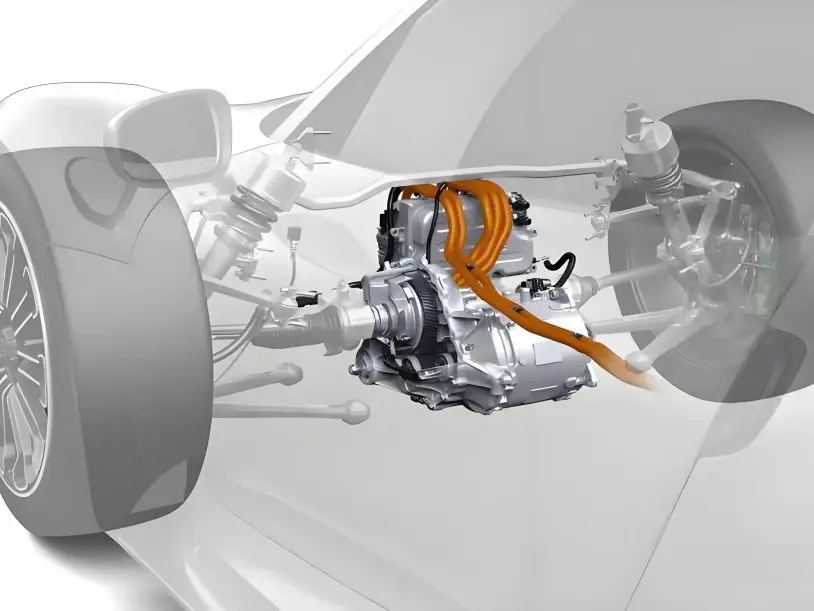
The main drive inverter is a key component for controlling the main drive motor. It converts the DC power of the battery pack into the AC power of the drive motor. The efficiency of the conversion largely determines the energy consumption performance of the vehicle. At the same time, the peak power of the main drive inverter combined with the high-performance main drive motor also determines the overall performance of the vehicle.
What is an Electric Vehicle Power Inverter?
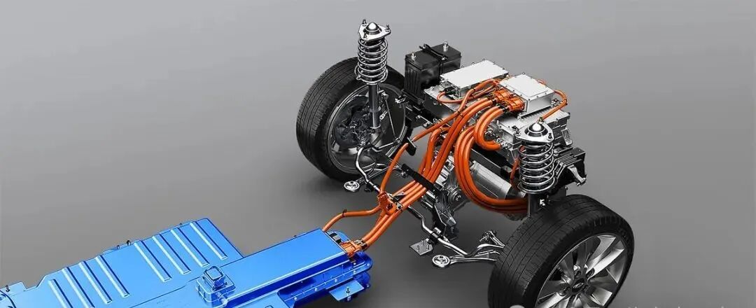
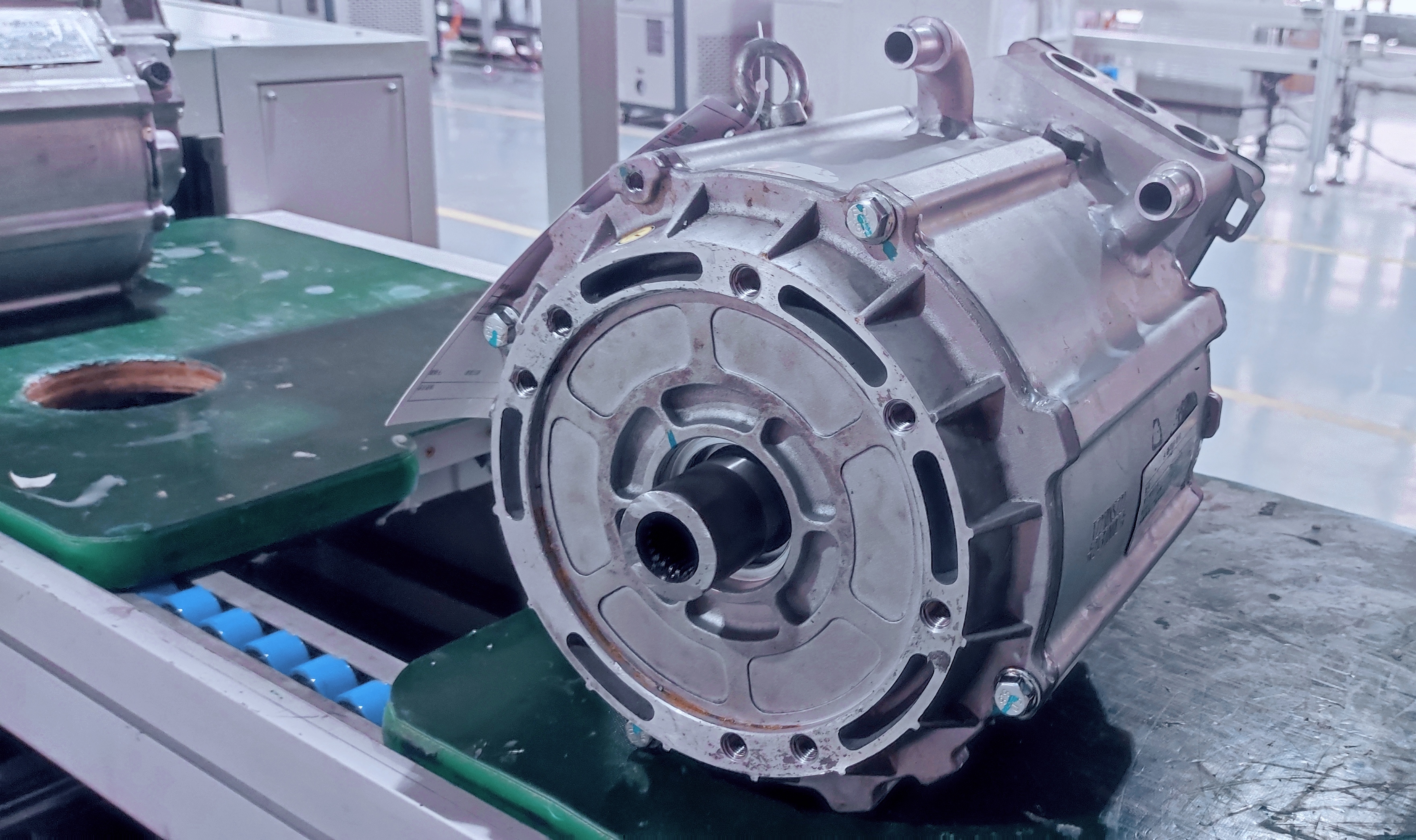
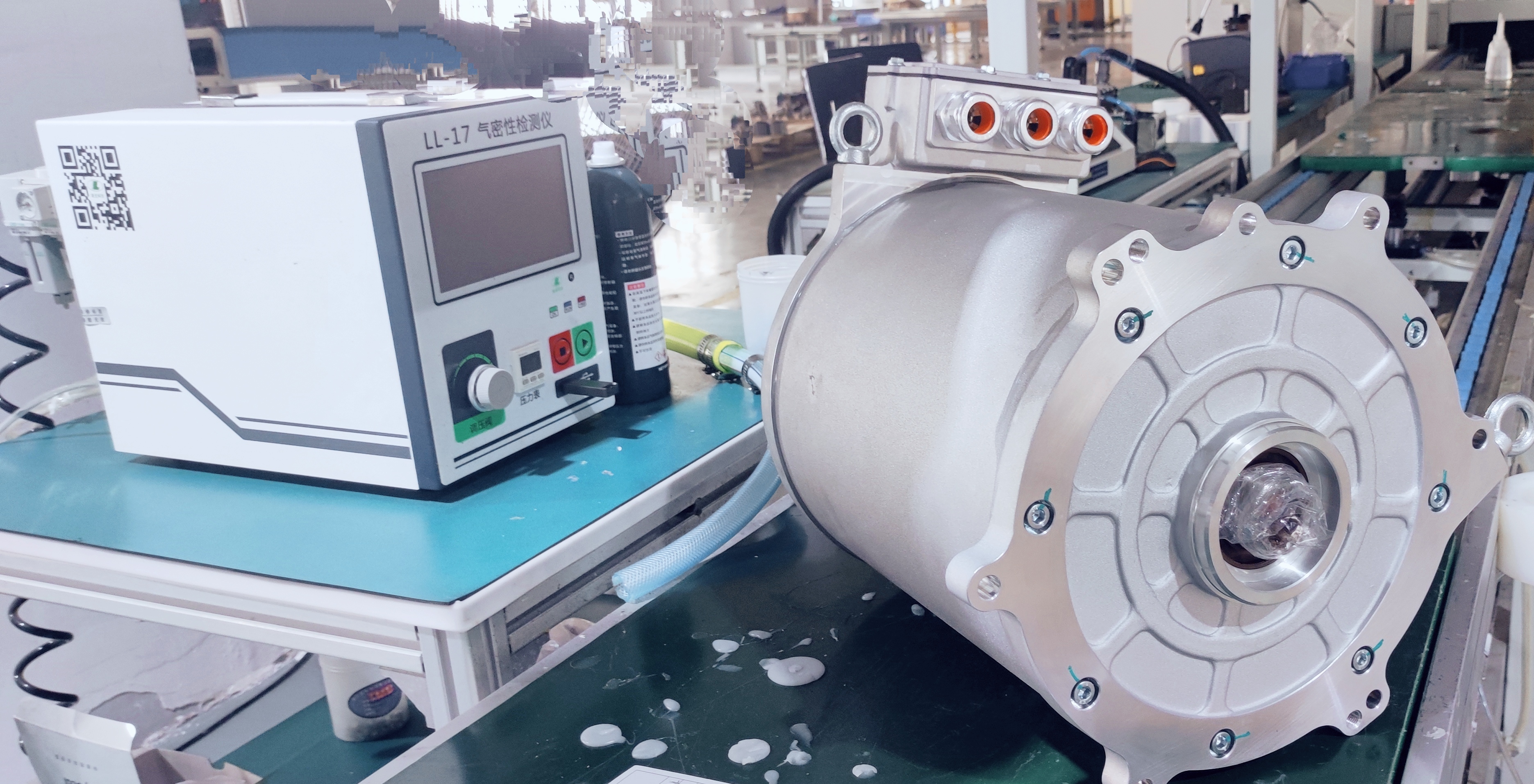
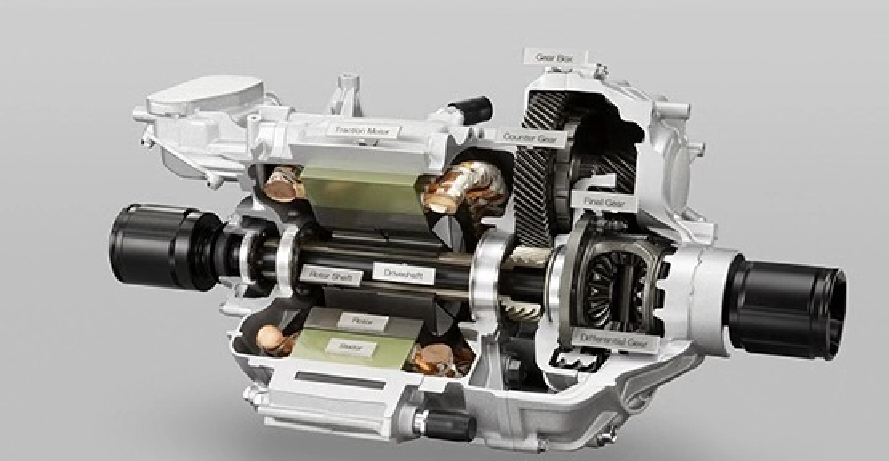
An electric car power inverter is a device that converts direct current (such as generated by batteries and storage bottles) into alternating current (such as 220V, 50Hz sine wave) with adjustable frequency. There are two types of power sockets used in life: 220V/110V. Although we have no way to store alternating current, we can store direct current in batteries and then use inverters to convert AC to DC. Due to the high voltage and high power of new energy power electric motors, AC motors that do not require brush commutators are used in consideration of higher efficiency and longer life. A rotating magnetic field can be generated on the stator through alternating current, thereby getting rid of the constraints of the brush commutator and driving the rotor to reach the required speed and torque under the action of the rotating magnetic field. The power motor inverter, an energy conversion device, converts the high-voltage direct current of the power battery into the alternating current required by the power motor.

3. How Does the Inverter Work in an Electric Car?
Working principle of electric car power inverter
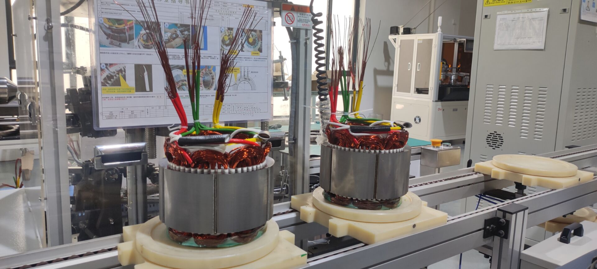
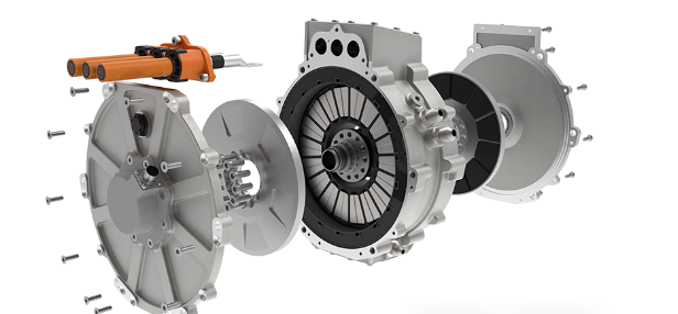
At the same time, the rotating magnetic field generated by the power motor inverter through alternating current must be precisely synchronized with the permanent magnetic field of the rotor, or controllably asynchronous with the induced magnetic field of the rotor. The rotor position sensor is the core of the reliable operation of the power motor inverter. The rotor position sensor is based on the principle of a rotary transformer and consists of multiple induction coils fixed on the stator and a metal cam disk fixed on the rotor. Each induction coil has an excitation winding and two secondary windings.

4. Main Functions of Electric Vehicle Power Inverter
The inverter has three main functions in the electric car:
1. Convert the DC power of the battery into three-phase AC power to drive the motor.
2. Change the torque and speed of the motor by changing the voltage and frequency through the inverter.
3. Convert mechanical energy into electrical energy to charge the battery during energy recovery.
AC Induction Motors in Electric Vehicles
In hybrid and pure electric vehicles, inverters are commonly used, as seen in models like Tesla, Toyota Corolla Hybrid, and BAIC EV160. The electric motors used in electric vehicles are driven by AC power. By changing the frequency and amplitude of the AC power, the speed and power of the motor can be adjusted. The higher the frequency of the driving voltage, the faster the speed of the motor, and the greater the amplitude of the driving voltage, the stronger the power of the motor. However, there is no way to store AC power. The batteries of new energy vehicles store DC power, which cannot be directly used to drive AC motors. Therefore, a converter is needed to convert the DC power in the car battery pack into AC power that can be used by the motor.
There are two main points in the design of vehicle inverter power supply. One is to increase the battery voltage to 220V, and the other is that the frequency must be 50Hz. To increase the voltage from 12V to 220V, a boost chopper circuit is used. The boost chopper circuit is used to achieve this. Since the output voltage is much higher than the input voltage, the boost factor is about 18. From the working principle of the boost circuit, it is easy to know that the duty cycle is about 0.95. It is theoretically feasible, but the boost circuit is difficult to implement in practice. Therefore, the boost must be achieved with the help of a transformer. If the transformer uses an industrial frequency transformer, the volume and weight will be much larger than that of a high-frequency transformer when the output power is the same, which is unacceptable to people. Therefore, a high-frequency transformer and a high-frequency conversion circuit are used. With the help of a high-frequency transformer, the voltage of 12V is converted to 220V, and the output frequency must also be high frequency. Many electrical devices that use 220V mains electricity cannot be directly used with high-frequency 220V AC. Further conversion is required to convert the high-frequency DC power into 50Hz AC. From the overall structure, the designed circuit has two parts: the first part converts 12V DC into 220V high-frequency AC with the help of a high-frequency transformer and the corresponding conversion circuit, and the second part converts the high-frequency 220V AC into 50Hz 220V AC.
5. Benefits of Electric Car Power Inverter
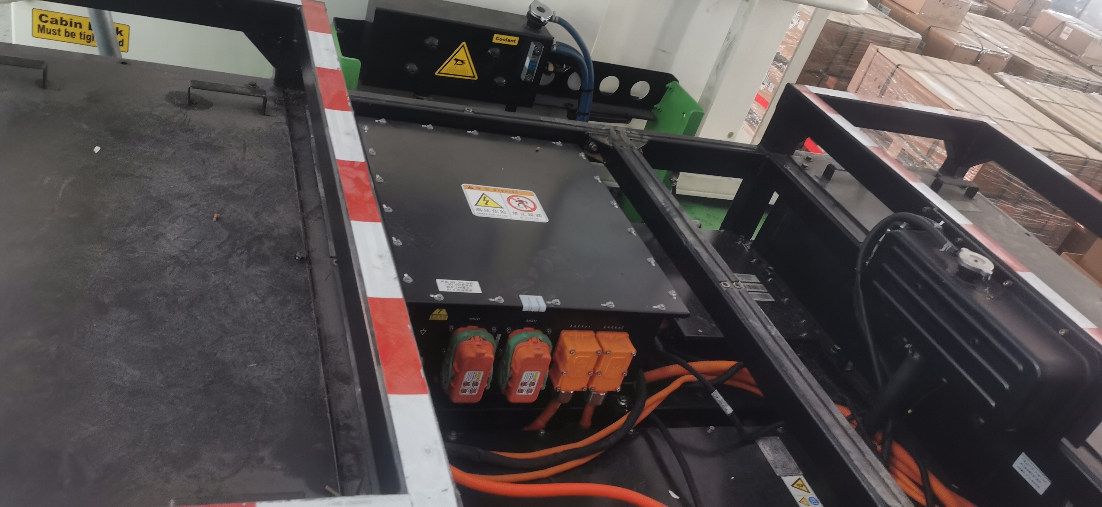
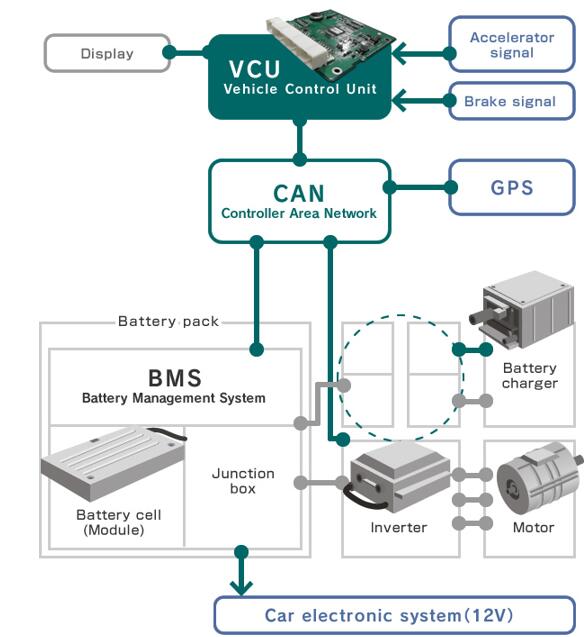
The inverter on a pure electric vehicle is located in the motor controller (MCU). In addition to the inverter, there is also a controller combined in the MCU. The MCU is the control center of the entire power system. The controller receives the demand signal of the drive motor. When the vehicle brakes or accelerates, the controller controls the frequency of the inverter to make the car move. The inverter receives the DC power output by the power battery, inverts it into three-phase AC power to provide it to the motor for operation, and plays the role of braking and recovering electric energy during the braking process of the electric vehicle. As shown in the figure below, the inverter is composed of 6 IGBTs, and the x model arrangement is Sa-Sc. Each phase output line (Ia, Ib and Ic) of the motor and the positive and negative DC lines are connected to an IGBT. The switching element IGBT in the inverter cannot function when its temperature exceeds 150 degrees, so air cooling or water cooling measures must be used. When the car reports a drive motor system fault, such as overheating of the drive motor, overheating of the drive motor coolant temperature, etc., then we need to use a diagnostic instrument to read the specific meaning of the fault code, because the fault displayed on the dashboard is not very specific.
6. Beyond Vehicles: Other Applications
The application of inverters is very extensive, covering multiple fields and specific application scenarios. The following are some of the main inverter application areas: photovoltaic power generation system , solar power generation , wind power generation , UPS system , aviation field , etc.
7. Emerging Trends in Electric Vehicle Power Inverter Technology
The main drive (main) inverter in an electric vehicle converts the DC battery voltage into AC voltage, thereby meeting the AC voltage requirements of the electric traction motor, enabling it to drive the vehicle smoothly. The latest trends in main drive inverter design include:
Increased Power: The greater the inverter's power output, the quicker the vehicle accelerates and the more responsive it is to the driver.
Maximize efficiency: Minimize the amount of electricity consumed by the inverter to increase the power available to drive the vehicle.
Increasing voltage: Until recently, 400V batteries have been the most common specification in electric vehicles, but the automotive industry is moving towards 800V to reduce current, cable thickness and weight. To do this, the main drive inverter in electric vehicles must be able to handle this higher voltage and use suitable components.
Reduce weight and size: SiC has a higher power density (kW/kg) than silicon-based IGBTs. Higher power density helps reduce system size (kW/L), reducing the weight of the main drive inverter while reducing the load on the motor. Reduced vehicle weight helps extend the vehicle's mileage with the same battery, while reducing the size of the drivetrain and increasing available space for passengers and the trunk.
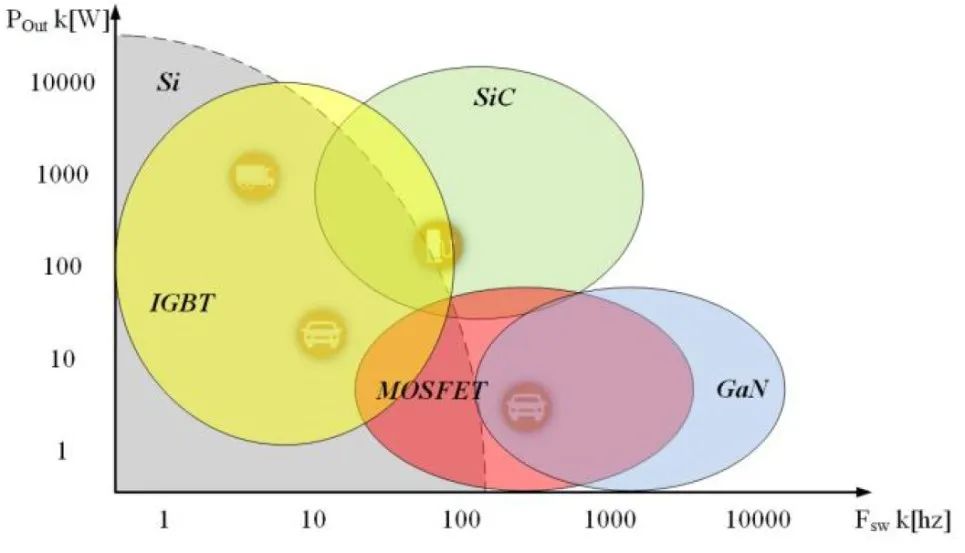
Compared with silicon, silicon carbide has several advantages in terms of material properties, making it a better choice for main drive inverter design. The first is its physical hardness, which reaches 9.5 Mohs hardness, while silicon is 6.5 Mohs hardness, so silicon carbide is more suitable for high-pressure sintering and has higher mechanical integrity . In addition, the thermal conductivity of silicon carbide (4.9W/cm.K) is more than four times that of silicon (1.15 W/cm.K), which means that it can transfer heat more effectively and operate reliably at higher temperatures. The breakdown voltage of silicon carbide (2500kV/cm) is more than 8 times that of silicon (300kV/cm), and it has a wide bandgap property that can turn on and off faster, making it a better choice for the increasingly high voltage (800V) architecture of electric vehicles. At the same time, the wider bandgap voltage means that it has lower losses than silicon. SiC-MOSFET has no tail current, high carrier mobility, and reduces device switching losses. The Si-IGBT module integrates a fast recovery diode (FRD), which will have reverse recovery current and tail current when turned off, resulting in limited switching speed and large turn-off losses. SiC material has a higher current density and a smaller package size at the same power level.
8. Challenges in Electric Car Power Inverter Development
In a traction inverter, the microcontroller (MCU) is the brain of the system, performing motor control, sampling voltage and current through analog-to-digital converters (ADCs), calculating field-oriented control (FOC) algorithms using magnetic cores, and driving power field-effect transistors (FETs) using pulse-width modulation (PWM) signals.
For MCU, the transition to 800V traction inverters brings three challenges: 1. Real-time control performance requirements with lower latency 2. Increased functional safety requirements 3. Need to respond quickly to system failures
Even in high temperature environments, our solution is still effective, which makes the application of small-scale inverters possible. At present, in the design of electric and hybrid vehicles, manufacturers have effectively solved problems such as energy endurance, power, reliability and cost-effectiveness with their professional knowledge and experience, and have been widely recognized in the industry.
We discussed with several senior engineers from OEMs in the field of battery pack development, and they proposed that the optimal driving range of electric vehicles is about 400 kilometers, and if the size and weight can be reduced, then electric vehicles may be more efficient. Based on this view, OEMs will consciously reduce the number of batteries to make the car lighter and more cost-effective while still meeting the range requirements.

As more electric vehicles are produced, the design trend will shift to SiC and 800V technology, while there is a need to improve motor control performance and meet functional safety requirements for traction inverters.
9. Future Outlook for Electric Vehicle Power Inverters
Some automakers are establishing partnerships with semiconductor/chip suppliers to move to SiC technology.
Geely: In 2021, Rohm Semiconductor and Geely announced a collaboration to develop SiC power devices. Under the partnership, Geely will use Rohm's SiC power devices in its drive inverters and on-board charging systems, aiming to extend the range of its electric vehicles.
General Motors: In 2021, General Motors signed a supplier agreement with Wolfspeed, Inc., in which Wolfspeed will provide SiC power devices for GM's Ultium Drive motors.
Mercedes-Benz: In 2022, ON Semiconductor announced that its SiC technology for inverters has been used by Mercedes-Benz in its all-electric VISION EQXX electric vehicle.
Volkswagen: In January 2023, Volkswagen established a strategic partnership with Onsemi. According to the agreement, Onsemi will provide Volkswagen with SiC power modules (EliteSiC power modules) and technologies for Volkswagen's next-generation electric vehicles.
The total global inverter demand will grow from 43.99 million units in 2023 to 120 million units in 2034, with a compound annual growth rate of 9.55%. Currently, IGBT inverters are the most widely used inverter type in all types of electric vehicles worldwide, followed by Si MOSFET. However, with the increase in demand for BEVs and the shift to 800V architecture, the demand for SiC inverters is likely to increase. By 2034, the market share of SiC and IGBT inverters will reach 44% and 45%, respectively, almost evenly divided.
10. Conclusion
As the demand for improved efficiency and extended driving range continues, the automotive industry will witness the majority of automakers’ electric vehicles switch to 800V architecture. Due to the high switching efficiency and low losses of SiC inverters, the demand will be strong and they will be widely adopted. The widespread adoption of SiC inverters will lead many automakers and suppliers to choose to vertically integrate with semiconductor companies to secure the supply of SiC.


