


News


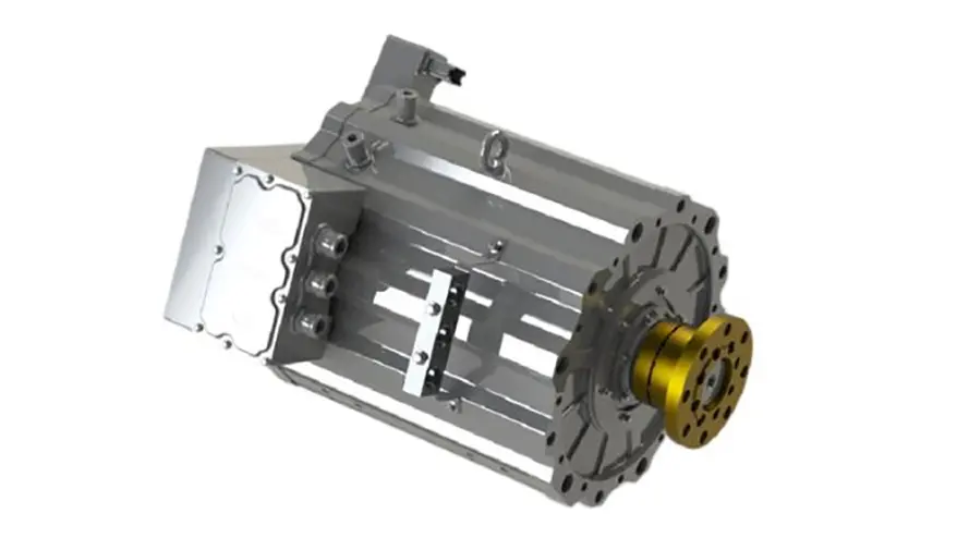


How to read the parameters of permanent magnet synchronous motor?
How to read the parameters of permanent magnet synchronous motor?
Understanding the parameters of permanent magnet synchronous motor (PMSM) is the basis of selection, application, control and fault diagnosis.
These parameters are usually divided into two categories:
Plate parameters/Basic performance parameters: These are usually directly marked on the motor plate or in the performance specification table of the product manual, which is most commonly encountered by users.
Design parameters/equivalent circuit parameters: These parameters are critical for in-depth analysis, precise control and simulation modeling of the motor. They are usually found in the technical appendix of the product manual, design documents, or require testing to obtain
The following explains these two types of parameters in detail:
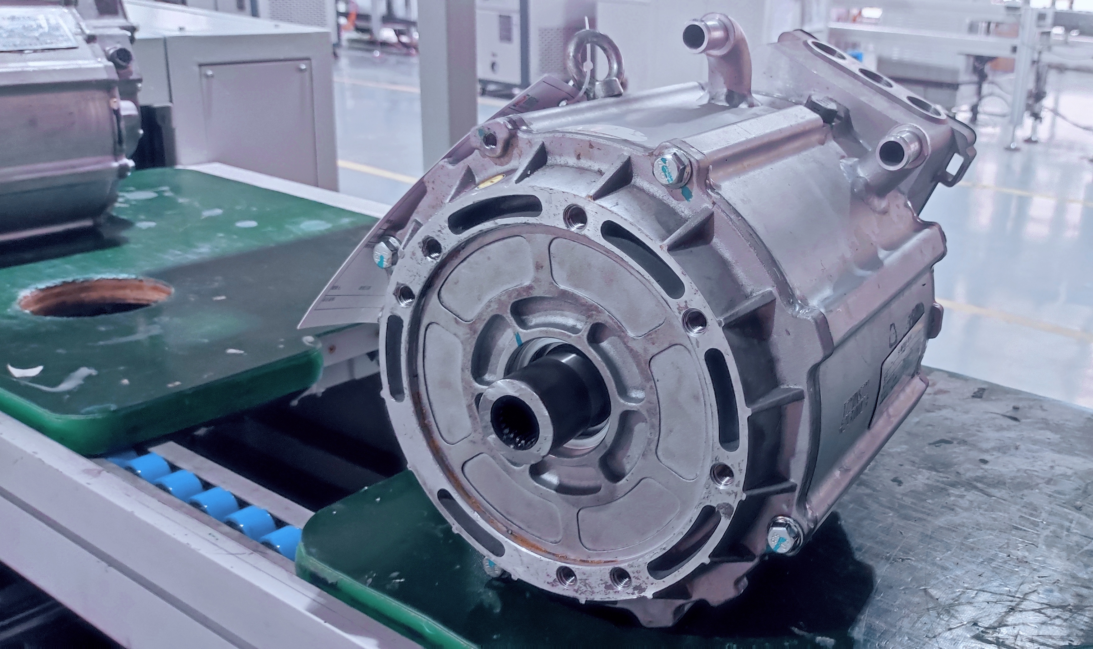
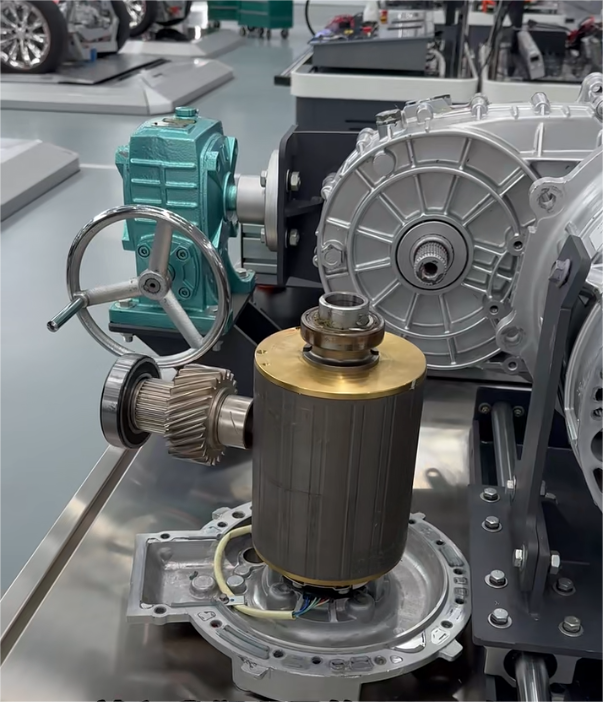
I. Nameplate parameters / Basic performance parameters
1. Rated power:
Meaning: The mechanical power that the motor can output continuously, safely and reliably under rated conditions (rated voltage, rated speed, rated load, specified cooling conditions, etc.). The unit is usually kilowatt or horsepower.
Viewed as: This is the core parameter for selecting a motor to meet load requirements. Ensure that the maximum continuous power required by the load is less than or equal to the motor's rated power. Note the distinction between rated power and peak power (short-term overload capacity)
2. Rated voltage:
Meaning: The effective value of the line voltage specified during design and applied to the stator winding of the motor. The unit is volt.
For a motor powered by the driver, this usually refers to the equivalent value of the inverter DC bus voltage converted to the AC side.
How to view: must match the output voltage capacity of the driver. Too high voltage will damage insulation or cause magnetic saturation; too low voltage will not be able to output rated power and torque, performance degradation.
3. Rated current:
Meaning: the effective value of the stator line current input from the power supply when the motor outputs the rated power, rated speed and rated voltage. The unit is ampere.
How to look: used to calculate the input power, select the driver current capacity (the rated current of the driver must be greater than the rated current of the motor), design the power supply line and overload protection device. It also indirectly reflects the size of copper loss.
Rated speed:
Meaning: The rotor rotation speed of the motor at rated voltage, rated frequency and rated output power. Unit is revolutions per minute.
It needs to match the speed requirements of the load. How to understand whether the motor is running at constant speed or not: it needs to be adjusted to run at speed. Note the difference between rated speed and maximum speed (limited by mechanical strength and weak magnetic capacity)
5. Rated frequency:
Meaning: The frequency of the power supply when the motor is directly powered by a sinusoidal power supply (e.g., the grid). For motors driven by a frequency converter, this parameter usually refers to the output frequency of the driver at rated speed.
How to view: For power frequency applications, it must match the grid frequency (50Hz or 60Hz). For variable frequency applications, this parameter is directly related to the rated speed (n = 60f /p, where p is the number of poles).
6. Rated torque:
The mechanical torque generated by the motor when it outputs the rated power at the rated speed. Unit: N · m.
The formula is: T = P/w, where P is the rated power (Watt) and w is the rated angular velocity (radian/second, w = 2πn/60, n is the rated speed in rpm). This is the core parameter required to overcome the load's zero resistance torque. Note the difference between rated torque and peak torque (short-term overload capacity).
7. Efficiency:
The motor's rated efficiency is defined as the percentage ratio of output mechanical power to input electrical power (Pin = √3 * V rated, where V is the rated voltage for three-phase systems). The formula n= (P_out / P_in) × 100% indicates its capability to convert electrical energy into mechanical power. Higher efficiency reduces energy losses (including copper losses, iron losses, mechanical losses, and leakage losses) while lowering operational costs. Note that the efficiency displayed on motor nameplates typically only reflects the rated condition.
8. Power factor:
Meaning: the ratio of input active power to apparent power (cosφ) under rated working conditions. It reflects the phase relationship between current and voltage waveform and the degree of current distortion.
How to look at it: A high power factor means a high utilization rate of the grid and less "pollution" to the grid. PMSM usually has a high power factor (close to 1) under rated conditions. The driver (inverter) itself also affects the power factor on the input side.
9. Frequency:
Meaning: The total number of magnetic poles (N and S poles appear in pairs) of the motor's magnetic field. The number of poles is usually indicated on the nameplate.
Viewing: Determines the relationship between the synchronous speed of the motor and the power supply frequency (n sync = 60f/p). More poles result in lower synchronous speed but potentially higher torque density. Parameters affecting control algorithms (e.g., observer bandwidth)
10. Insulation class:
Meaning: The maximum operating temperature of the insulation material of the motor winding is specified. Common grades are B (130°C), F (155°C), H (180°C).
How to look: Determines the allowable temperature rise and overload capacity of the motor. In high temperature environment or applications requiring high overload, it is safer and more reliable to choose a motor with higher insulation grade (e.g. F or H).
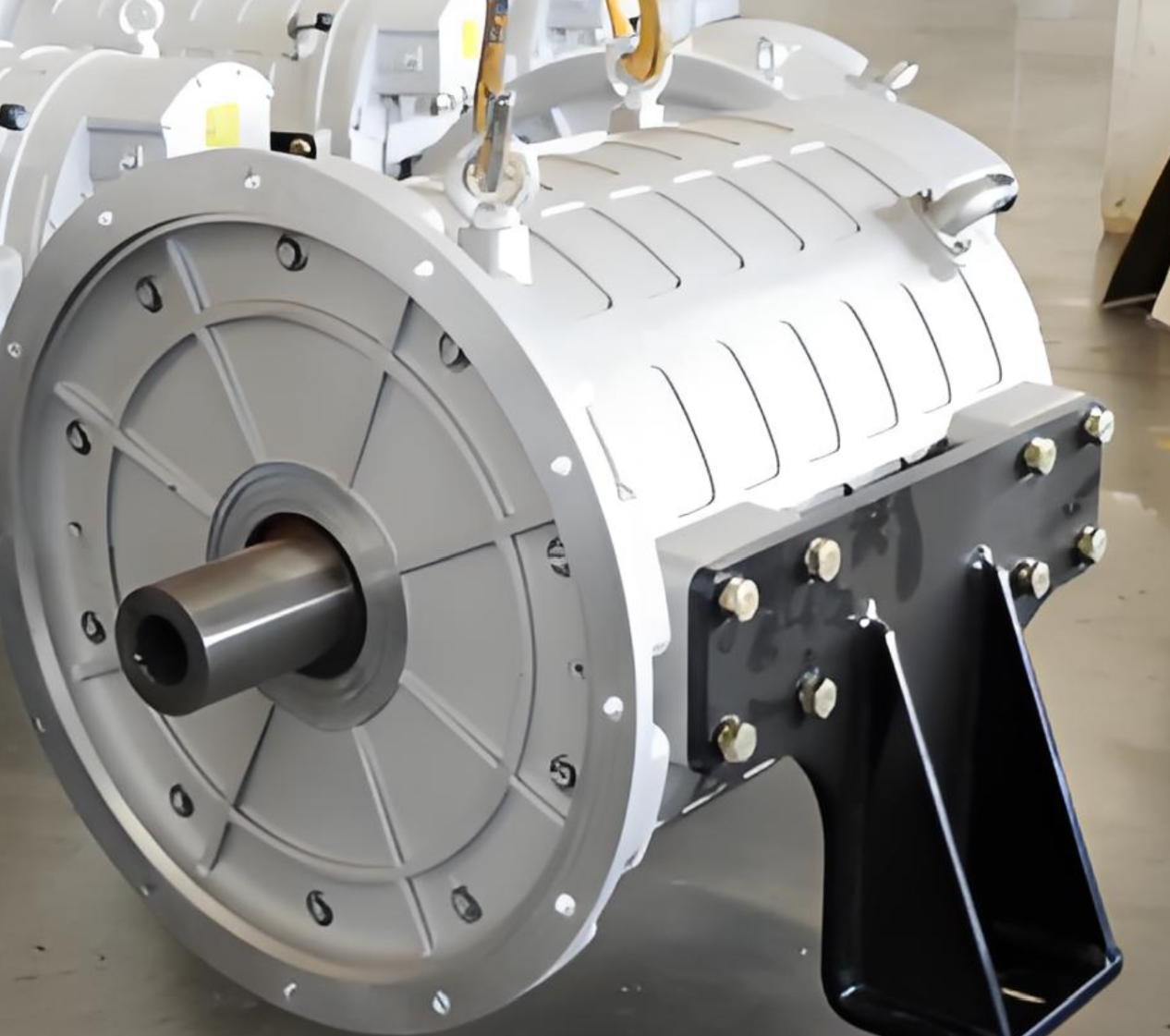
11. Protection class:
Meaning: The IP code indicates the motor housing's ability to prevent solid foreign matter (first digit) and liquids (second digit) from entering. For example, IP54 (dustproof and waterproof), IP65 (dustproof and water-resistant), IP67 (dustproof and short-term immersion resistant).
How to look: Select according to the dust, humidity and moisture conditions of the motor installation environment. Outdoor, humid and dusty environments require high protection class (such as IP65 or higher)
12. Cooling mode:
Meaning: The way of motor heat dissipation. Common ones are I0 411 (self fan cooling, surface heat dissipation), I0 416 (forced air cooling, external fan), I0 410 (natural cooling, no fan), IC71W (water cooling).
How to look: It affects the power density and continuous operation capacity of the motor. High power or compact motors are often forced air cooling or water cooling
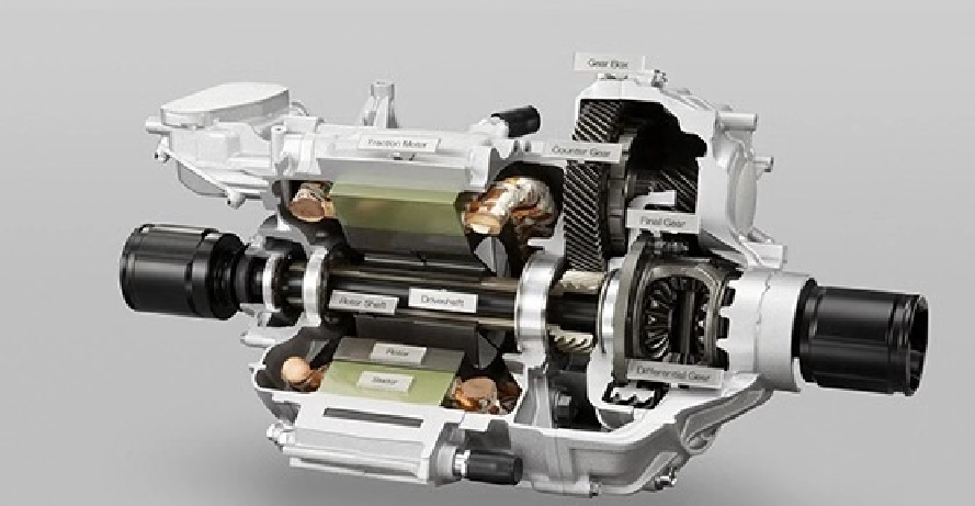
II. Design parameters/equivalent circuit parameters
These parameters are usually used to establish the mathematical model of the motor (d-q axis model) for vector control, simulation, efficiency optimization and performance prediction.
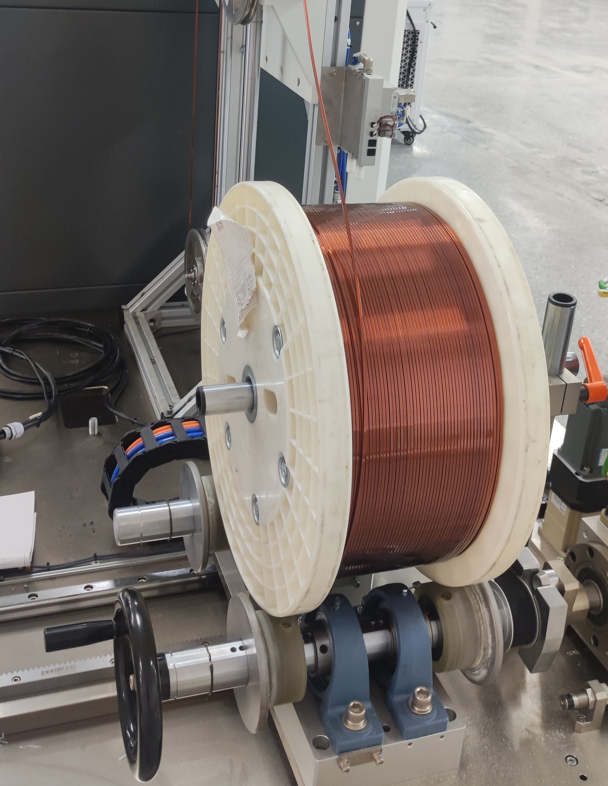
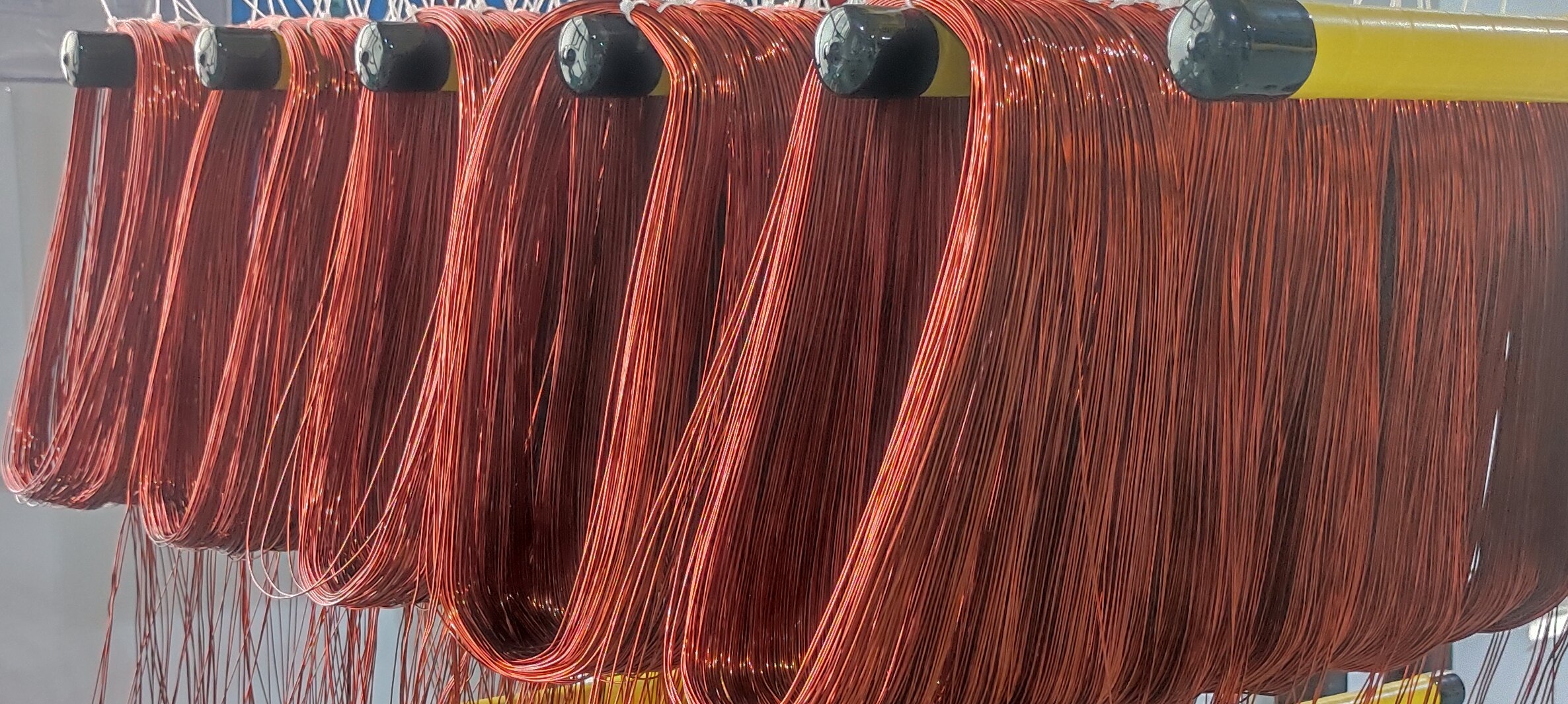
1. Stator resistance:
Meaning: The resistance value of each phase of the stator winding under DC or low frequency. The unit is ohm. Usually refers to phase resistance.
How to look at it: It affects the calculation of copper loss, the setting of current loop control parameters and the estimation of temperature rise. It is significantly affected by temperature (increasing with temperature)
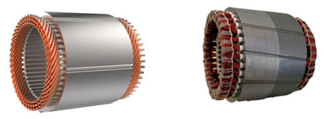
2.D-axis inductance / Q-axis inductance:
Meaning: The stator inductance parameter defined in the rotor rotating coordinate system (d-axis and q-axis). The d-axis is along the direction of the permanent magnet's magnetic field, and the q-axis is 90 degrees electric angle ahead of the a-axis.
Ld: D-axis inductance. Due to the presence of permanent magnets, the magnetic reluctance of the D-axis magnetic circuit is large, and Ld is usually small or even negative (for embedded PMSM)
Q-axis inductance. The Q-axis magnetic circuit mainly passes through the stator and rotor cores, with low magnetic resistance, and Lq is usually large. La:
Key parameters determine: Electromagnetic torque: T=(3/2)×p[Ψ±×lq + (Ld-Lq)×ld×lq] (where Ψ± represents the permanent magnet flux linkage). The fundamental principle of PMSM generating reluctance torque lies in Ld = Lq (for IPMSM with high salient pole ratio). Weak magnetic capability: Smaller Ld values typically enable broader weak magnet operation ranges and superior high-speed performance. Current loop bandwidth and controller design: Inductance constitutes the primary time constant in the current loop's first-order inertia component. Electromagnetic back EMF waveform and amplitude are significantly influenced by magnetic saturation levels (particularly at high currents).
3. Permanent magnet flux:
Meaning: The amplitude of the magnetic link generated by the permanent magnet in the stator winding. The unit is Weber. Usually refers to the maximum magnetic link induced by the rotor permanent magnet field in the stator winding.
How to look: Core parameters! It determines:
Back EMF constant: Ke = Ψpm * w (where w is the angular velocity of the electric field). Back EMF is proportional to the rotational speed.
Torque constant: Kt ≈ (3/2) * p * Ψ ± (for surface-mounted SPMSM, Ld ≈ Lq). Torque is proportional to the q-axis current.
Base speed: The maximum speed that the motor can achieve at rated voltage (when the back EMF is close to the bus voltage)
The starting point of weak magnetic control.
4. Back EMF constant:
Definition: The magnitude of the back EMF (typically referring to line back EMF) generated per revolution by a motor. Units are V/(krpm) or Vs/°. Measurement Method: Directly related to permanent magnet flux linkage Ψpm (Ke= Ψpm × w). Used to estimate back EMF at any rotational speed (E = Ke × n), which is crucial for determining the minimum bus voltage required by drives, preventing overmodulation, and implementing weak magnet control. Measurable through no-load back-drive testing.
5. Torque constant:
Meaning: The magnitude of the torque generated by the motor per unit current (for SPMSM, approximately Kt ≈ (3/2)*p*Ψpm). The unit is Nm/A.
Reference: Used to estimate the q-axis current command required for a given torque command (lq_ref =T_ref / Kt). Note that for IPMSM, Kt is not constant due to the existence of magnetoresistance torque and varies with Id.
6. Electrical time constant:
Meaning: usually refers to the electrical time constant of the current loop, T_e=L / R (L is usually taken as Lq or average, R is the phase resistance)
How to look: It is a key parameter of the design current loop controller (usually PI regulator), which determines the response speed of the current loop.
7. Mechanical time constant:
Meaning: Considering the time constant of motor and load inertia, friction and other factors, Tm=J*R/(Kt *Ke) (J is the total inertia)
How to look: The response speed of the speed ring is an important reference for the design of the speed ring controller
8. Moment of inertia:
Meaning: The moment of inertia of the motor rotor itself. Unit is kg·m? How to read: It affects the acceleration/deceleration capability of the motor, dynamic response of the speed loop, and sensitivity to load disturbance. The servo system has requirements for matching the moment of inertia.
9. Maximum current:
Meaning: The maximum short-term current (peak current) allowed by the motor or driver. Usually much greater than the rated current.
How to view: Determines the short-term overload capacity (peak torque) of the motor. It is restricted by factors such as winding heating, permanent magnet demagnetization risk, and driver current limit.
10. Rotation inertia:
Meaning: the moment of inertia of the motor rotor itself. Unit is kg·m?
How to look at it: It affects the acceleration/deceleration ability of the motor, the dynamic response of the speed ring, and the sensitivity to load disturbance. The servo system has requirements for the matching of rotational inertia.
11. Maximum speed:
Meaning: the maximum speed that F motor can reach under the requirements of mechanical strength, bearing life, vibration and noise. Usually much higher than the rated speed.
How to view: Determines the operating speed range of the motor. At the highest speed, weak magnetic control is usually required to maintain torque output.
How do you look at these parameters
1. Clear purpose:
Selection and matching: Focus on the parameters of the nameplate (power, voltage, speed, torque, protection, cooling) to ensure that the load requirements, environmental conditions and power supply requirements are met. Focus on efficiency (long-term operating costs)
Drive configuration and control: In addition to the nameplate parameters, design parameters (R, Ld, Lq, Ψpm) must be obtained as the basis for achieving high-performance vector control (e.g., F0C). Controller parameters (PI gain, or Ke/Kt) and observer parameters need to be set according to these parameters.
Performance analysis and simulation: A complete set of equivalent circuit parameters (R, Ld, Lq, Ψpm, y, friction coefficient, etc.) is required to establish an accurate mathematical model.
Fault diagnosis: parameter changes (such as increased resistance may indicate overheating of the winding, and changes in inductance may indicate inter-turn short circuit or demagnetization) can be used as diagnostic basis.
2. Pay attention to the relationship between parameters:
Power, speed, torque: P=T*w
Voltage, back EMF, current, inductance: V ≈ E+ IR + jwLI (vector relationship)
Torque, magnetic flux, current: T=(3/2)*p*[Ψ± * lq + (Ld-Lq)* ld * lq] speed, frequency, pole logarithm: n_sync = 60f/p back electromotive force constant and magnetic flux: Ke∝ Ψ±
3. Understanding the conditional nature of parameters:
Many parameters (particularly design parameters R, Ld, and Lq) are not constants—they vary with temperature, current (magnetic saturation), and rotor position (tooth groove effect). High-performance control must account for these nonlinear factors. Specifications on equipment nameplates are defined under specific conditions (rated voltage, frequency, load, cooling, and temperature). When actual operating conditions differ from these ideal scenarios, performance may deviate from the rated point.
4. Look up official documents:
Motor specifications are detailed in the equipment nameplate and performance specifications table within product manuals. Critical design parameters (R, Ld, Lq, Ψpm, Ke, Kt) are typically provided in the "Technical Parameters", "Equivalent Circuit Parameters", or "Control Parameters" sections of the manual. If unavailable, manufacturers' documentation must be obtained. Detailed parameters such as inductance curves at different saturation levels may require specialized design documents or test reports.
5. Test measurement:
If the official parameters cannot be obtained, experimental measurements (such as block test, no-load drag test, LCR meter measurement, parameter identification algorithm, etc.) are required. However, this requires professional equipment and knowledge.