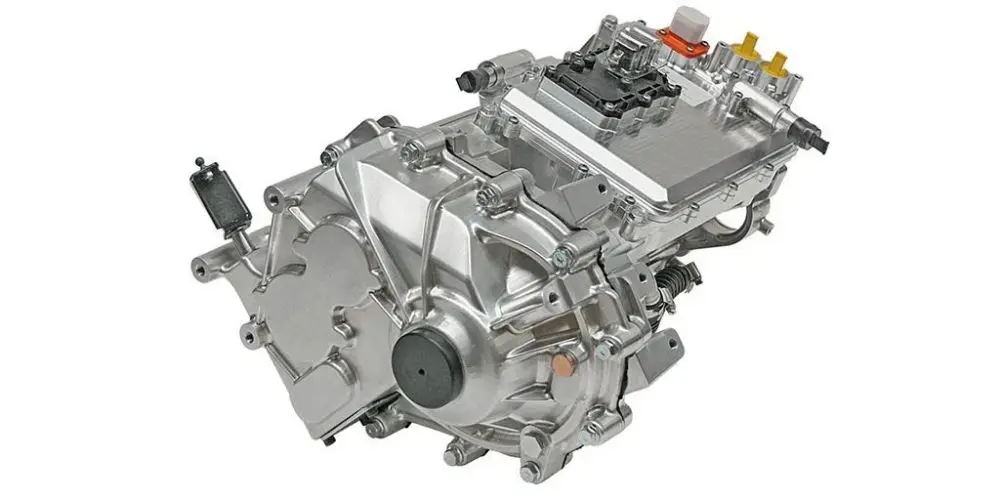
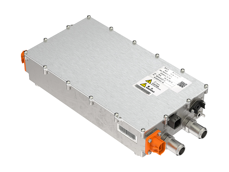
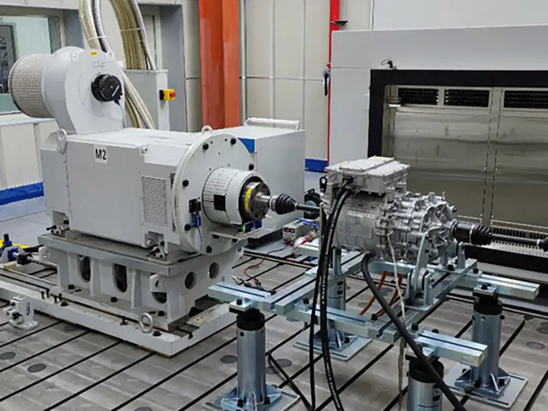
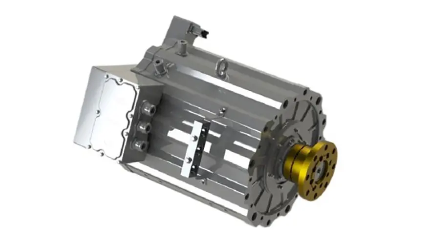
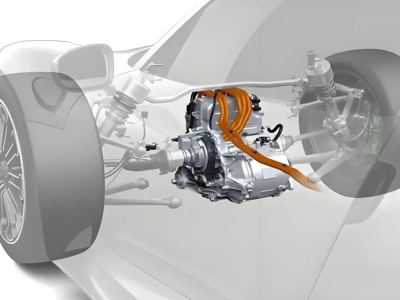
SiC+Si mixed carbon fusion inverter · Panorama analysis from concept to system solution implementation
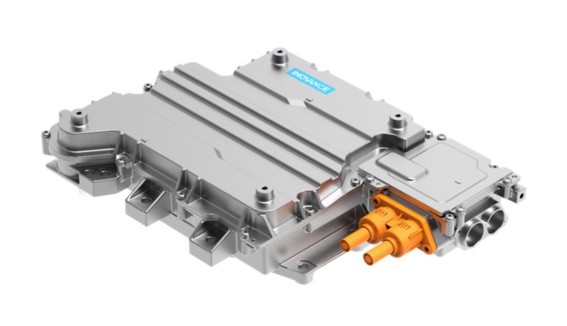
With the rapid advancement of electric vehicle technology, innovation and optimization of power devices have become key drivers for industry progress. The SiC (Silicon Carbide) and Si (Silicon) multi-variable hybrid inverter technology, as a highly forward-looking innovative achievement, is gradually gaining prominence in the electric vehicle sector.
I: What kind of inverter does the market need?
1.China's electric vehicle development trend and power semiconductor demand
China's electric vehicle market has entered a phase of explosive growth, emerging as a pivotal driver in the global transition to new energy. As shown in the chart below, sales surged from tens of thousands to 12.87 million units over the decade from 2013 to 2024, driven by policy support, heightened consumer environmental awareness, and technological advancements. Passenger vehicles continue to see their market share in EVs steadily climb, with electric vehicles accounting for 40.9% of new car sales by 2024. The market is shifting from policy-driven initiatives to demand-led growth, with consumer acceptance reaching unprecedented levels.
In the market segment, PHEV and REEV have achieved an 84.69% growth rate over the past two years. Their "flexible charging" feature—using pure electric mode for urban commuting to reduce costs while employing fuel-powered charging for long-distance travel to alleviate range anxiety—suits diverse user scenarios. Regarding voltage platforms, the 800V high-voltage platform's market share has surged from 2% in 2022 to 15% by 2025. With rapid charging capabilities (over 300kW) and significant energy efficiency improvements, it effectively meets the demands of premium vehicles.
With consumers 'electric vehicle demands becoming increasingly diverse, there's a growing preference for "larger cabin space" and "stronger power output". This trend drives the evolution of powertrains towards being "smaller, more powerful, more efficient, and more cost-effective". After analyzing market trends, how have the key performance metrics of inverters—core components in electric drive systems—developed? Let's explore the roadmap for inverter KPI evolution in detail.
2.Inverter KPI development roadmap: rate semiconductor innovation direction
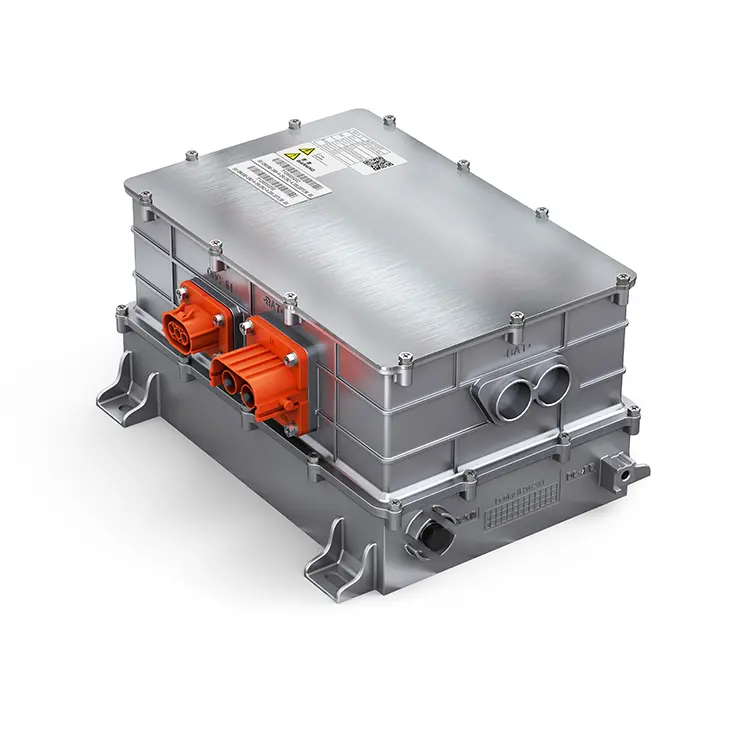
As a critical component in electric vehicles, traction inverters directly determine the vehicle's power output, energy efficiency, and driving experience. Optimizing their performance has become a vital strategy for automakers and suppliers to enhance competitiveness. Let's examine the key KPIs of inverters: cost efficiency, power density, and cycle efficiency. What are the current development trends in these areas?
The chart below shows the changing trend of inverter core KPIs from 2019 to 2027. Through the "Inverter KPI Roadmap", we can clearly capture:
- Cost: Since 2019, the price of Si IGBT has decreased by 65%, and the price of SiC has decreased to a certain extent, but it is still about 2.5-3 times more expensive than Si IGBT.
- Power density: The inverter power density curve shows an upward trend, from 37 kW/L in 2019 to 100 kW/L in 2027, helping to achieve more compact and efficient inverter designs.
- CLTC-P efficiency: The efficiency curve of SiC is expected to increase from 95.8% in 2019 to 99.2% in 2027; the efficiency of Si is also improved, but it is always lower than that of SiC.
3.What are the factors that affect the changes of these KPIs? There are several main aspects (the following focus points):
- Development of integration technology: including IC integration, mechanical integration, reduced connections, etc. -> helps to simplify the system structure, reduce unnecessary energy loss and signal interference, thus reducing costs, improving system reliability and power density
- Supply chain stability and optimization: scale effect, internal design, local supply and other factors can effectively control costs and ensure stable supply of components; by expanding production scale and optimizing supply chain layout, the cost of SiC and Si components can be reduced
- Innovative approaches: Such as chip embedding in PCB configurations, software algorithms (e.g., DPWM, square wave control, carrier frequency optimization, slope control), next-generation Si/SiC chip technology, low-leakage inductor packaging and layout, integrated power devices, three-level topology → These advancements enhance device performance and reliability, providing solid
technical support for inverter performance improvement. Therefore, we can perceive that the performance leap of inverters stems from power device technology evolving from "single-point breakthroughs" to "system synergy": the large-scale cost reduction of Si-based IGBTs, the efficient breakthrough of SiC, and the synergy of various innovative technologies collectively form the "three-dimensional competitiveness" of inverter technology. In this transformation, whoever achieves "triple optimization" in cost, efficiency, and integration will seize the initiative in electric vehicle drive systems and lead the industry to a higher-dimensional stage.
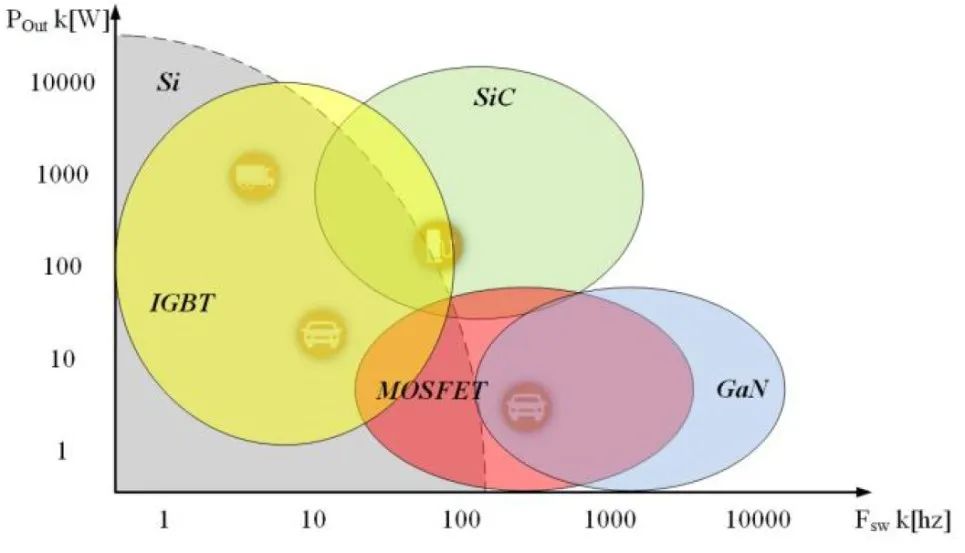
II: Topology of Si/SiC hybrid switch
The hybrid switch is composed of Si IGBT and SiC MOSFET in parallel. Through reasonable topology design and driving strategy, the advantages of both are complementary. Therefore, the design definition of topology structure is crucial!
This topology not only enhances the current-carrying capacity of switching devices but also reduces conduction and switching losses, thereby improving overall system performance and efficiency. Therefore, it is essential to analyze different topologies and study real-world applications of hybrid switches in inverters to demonstrate their significant effects in boosting inverter efficiency and reliability.
Si/SiC mixed switch device characteristics
After exploring various hybrid drive topologies, this analysis will focus on Si IGBT and SiC MOSFET configurations to detail the technical approach. Let's begin by understanding three fundamental questions: What are the switching characteristics of Si IGBT combined with SiC MOSFET? What makes these characteristics unique? And how can we leverage their individual strengths to achieve optimal performance?
Conduction Characteristics: Due to their distinct physical structures, IGBTs and SIC MOSFETs exhibit different output characteristic curves as shown in the figure below. SiC MOSFETs demonstrate more resistive conduction characteristics, while IGBTs feature a pronounced knee voltage (Knee Voltage) behavior. This technical difference manifests as distinct conduction loss characteristics between the two devices:
At low current, SiC mosfet has smaller on loss; when the current is large (over the intersection point of the curve), IGBT has smaller on loss.
IGBT and SIC MOSFET conduction characteristics
Switching characteristics: IGBT is a bipolar device, and the recombination of minority carriers will definitely cause trailing current when it is turned off, resulting in poor switching loss characteristics. However, SiC MOSFET has faster switching speed and no trailing current, so its switching loss has obvious advantages compared with IGBT
In conclusion, SiC MOSFET devices do not have overwhelming performance advantages under all load conditions. It is easy to understand that a break-even point needs to be considered when choosing between SiC MOSFET and Si IGBT.
Three: timing management and control strategy of hybrid switch
Once we have a deep understanding of device characteristics and the proper way to apply them at the system level, the next step is to consider how to implement these design ideas? There are three key issues: current ratio, timing management, and control strategy.
- Current ratio essentially addresses: How to maximize the output capability of power switches while ensuring their safe operation? Using Infineon's 1200V devices as a case study, this analysis demonstrates the actual switching performance of four hybrid devices on a dual-tube parallel dual-pulse test platform. The results illustrate how current capacity influences distribution under different hybrid current ratios, while also considering the safe operating range of the devices.
- Detailed description of Si/SiC device characteristics: 2.5 Optimal loss in asynchronous switching
Clocking management is a critical component in Si/SiC hybrid switch design. By precisely controlling the switching timing of Si IGBTs and SiC MOSFETs, we can achieve Zero Voltage Switching (ZVS) in IGBTs, thereby significantly reducing switching losses. The key questions are: How to optimize hybrid switch losses through asynchronous switching strategies? What are the different switching modes (switching timing choices)? How do varying turn-on and turn-off delays affect on-state and off-state losses in hybrid switches? These are the critical aspects we need to address.
Finally, we will introduce several innovative hybrid driver ICs available in the market that enable synchronous or asynchronous operation of SiC MOSFETs and Si IGBTs while incorporating advanced timing management capabilities. By dynamically adjusting on/off delay times and priority sequences in real-time, these ICs optimize switching performance across hybrid devices, thereby enhancing system efficiency and reliability.
Conclusion
As can be seen from the above introduction, in order to fully and systematically understand the technical direction of SiC-Si hybrid power semiconductor, our overall idea is to take three steps.
Step 1: Start with the most basic components. First understand them in depth and then discuss: What are their individual characteristics? How do they perform in parallel? How can we use the characteristics of these components to optimize system performance?
Step 2: After understanding the device characteristics and performance under different switching modes, we move to the inverter level. Building on our analysis at the device level, this section explores how to maximize transistor output characteristics through optimized SIC/SI ratios and drive strategies tailored to application conditions, while achieving higher system efficiency and reduced power loss. How can we fully leverage the current-carrying capabilities of SiC MOSFETs and Si IGBTs under various load conditions to achieve optimal balance between efficiency and performance?
Part III: Having gained a thorough understanding of device characteristics and system-level application approaches, the next critical question is how to implement these design concepts. This section will examine how to achieve efficient operation of hybrid SiC-Si power devices through well-designed control strategies and driver circuit architectures, focusing on driver ICs and circuit design.
Ultimately, the critical question remains: What are the practical applications and future prospects of Si/SiC hybrid switches in electric vehicles? As the EV market continues to expand and new energy technologies advance, the demand for high-efficiency, high-power-density, and highly-reliable switching devices will keep growing. With their superior performance and cost advantages, Si/SiC hybrid switches may soon become the dominant switching solution, injecting fresh momentum into product innovation and technological upgrades.


