


News


The Engineering Behind Mass-Produced 30,000 RPM Motors: A Complete Breakdown of 1000 MPa Rotors and Methodologies
Every breakthrough in performance limits stems from engineering logic that is decomposable and reproducible, from the doubling of material strength to the synergy of five major systems.
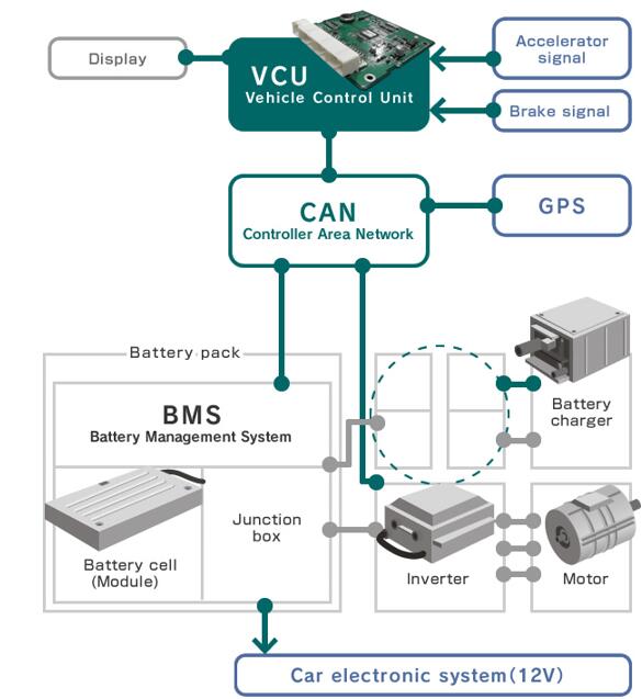
The mass production of 30,000 rpm motors represents a collaborative leap in engineering across materials science, electromagnetic design, thermal management, precision manufacturing, and control algorithms. PUMBAAEV has systematically redefined the boundaries of high-performance permanent magnet electric drive technology through doubling rotor material strength, a double-layer U-shaped magnet topology, 10-layer unequal-pitch hairpin windings, ultra-thin silicon steel laminations, and in-house developed 1500V SiC chips.
The boundary of technology is always beyond the next iteration. For engineers, the value of this case lies in this: behind every seemingly "extreme" performance metric, there is a decomposable, reproducible engineering methodology.
1 Overview: The Core Value of High Speed
With the widespread adoption of new energy vehicles, user demand for track scenarios and sustained high-speed operation has significantly increased. Traditional automotive motors experience a power "inflection point" around 6,000 rpm, with torque continuously decaying in the constant power region, leading to noticeably weakened acceleration feel during high-speed overtaking above 120 km/h.
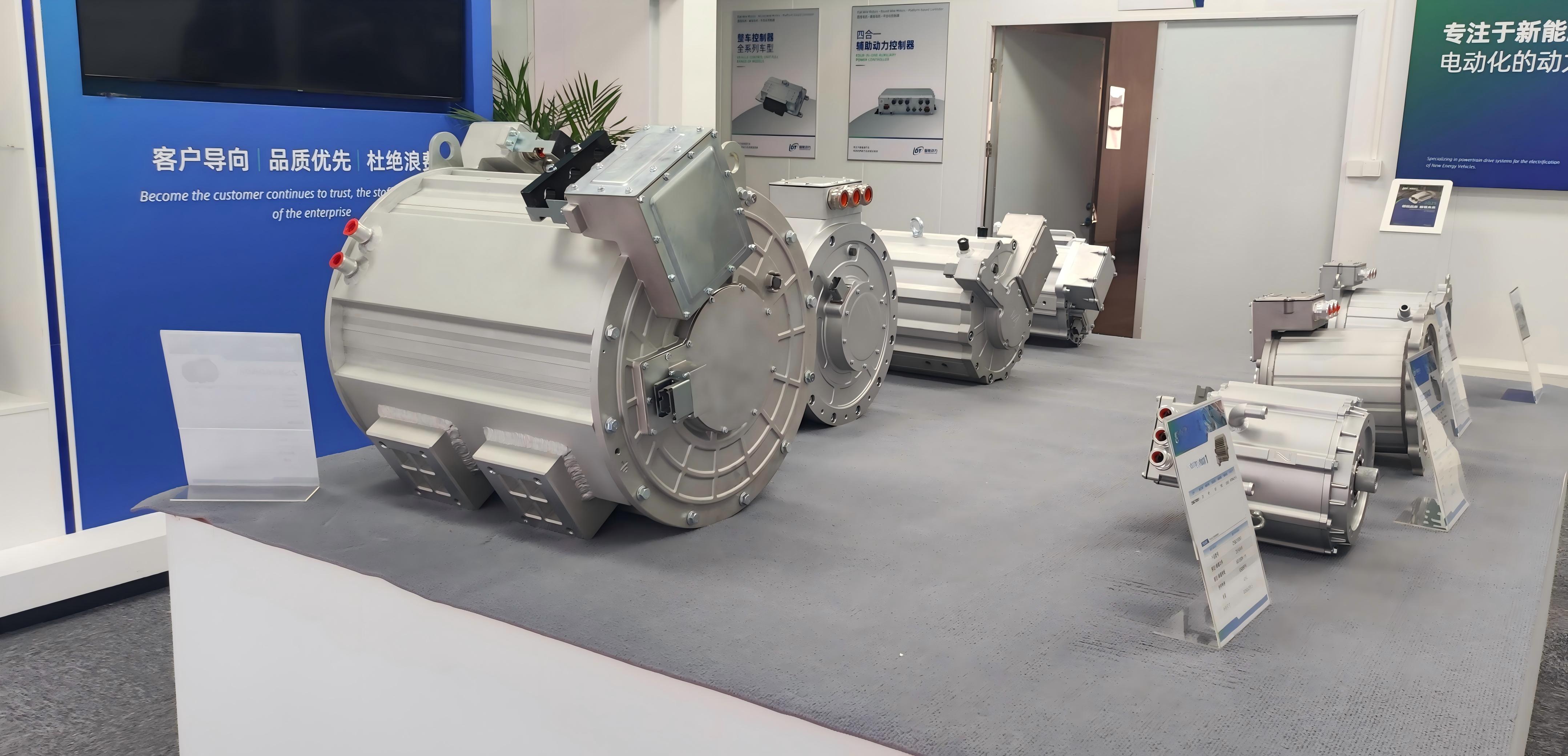
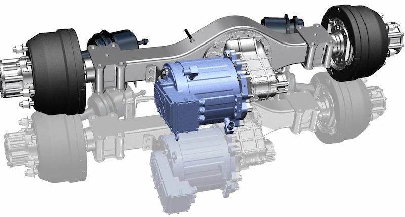
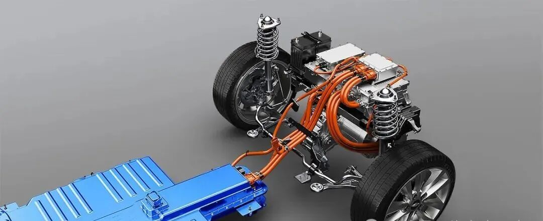
PUMBAAEV defined and developed a 30,000 rpm-class electric drive unit. Its core benefits extend beyond pure performance. From a systems engineering perspective, at the same target output power, increasing speed from 12,000 rpm to 30,000 rpm allows for a substantial reduction in the usage of active motor materials (copper, rare-earth magnets, silicon steel).
According to AVL research data, doubling the rotational speed can reduce iron core material usage by approximately 40%, achieving synergistic optimization of volume, weight, and cost.
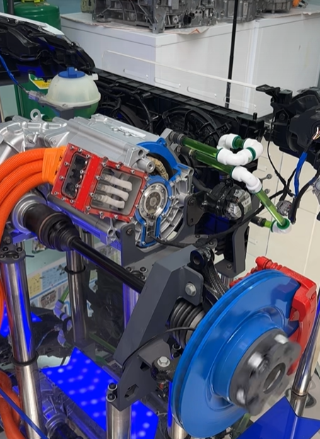
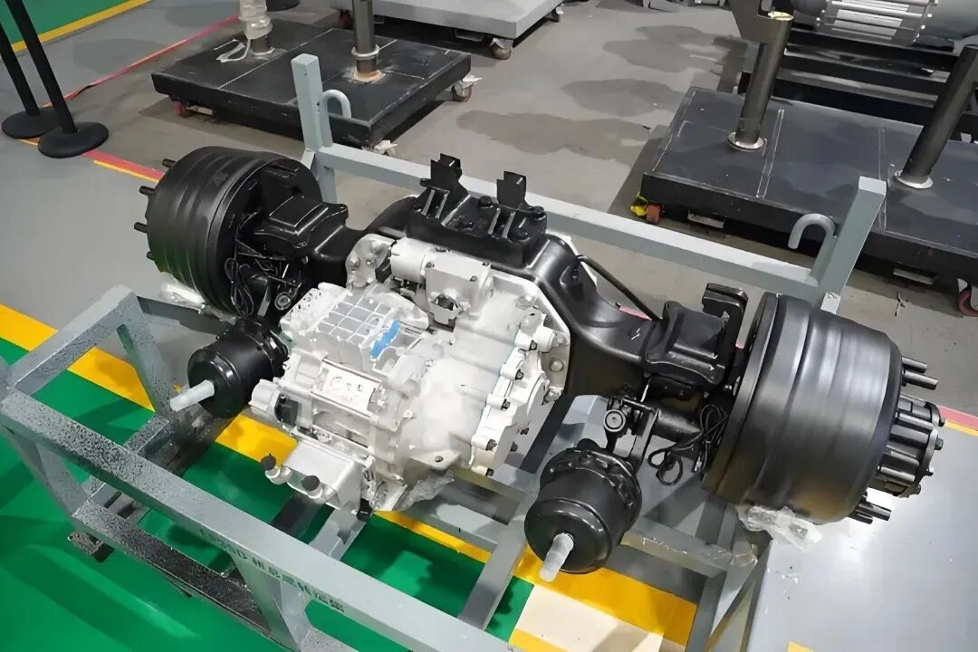
2 Rotor System: Five Core Engineering Challenges
The rotor is the most fragile yet critical subsystem in a high-speed motor. At 30,000 rpm, the centrifugal acceleration at the rotor's outer edge exceeds 40,000 g. Any design flaw can lead to catastrophic failure. Overcoming this challenge requires breakthroughs in five technical areas.
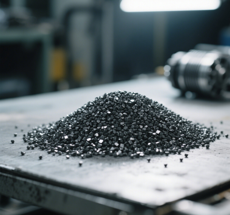
Challenge 1: Material Strength Doubling, from 450MPa to 1000MPa High-Strength Silicon Steel
Traditional rotor laminations use non-oriented electrical steel with a yield strength of about 450 MPa, sufficient for speeds up to 20,000 rpm. Beyond 30,000 rpm, the hoop tensile stress at the rotor's outer diameter exceeds the yield limit of conventional materials.
Engineering Breakthrough Path:
-
Material Upgrade: Adoption of High-Strength Electrical Steel (HS-ECS), increasing tensile strength to ≥1000 MPa—more than double the conventional industry level.
-
Process Support: Implementation of laser welding for lamination stacking instead of traditional riveting, enhancing interlayer bonding force to prevent separation at high speeds. Precision outer diameter grinding achieves a tolerance of ±3 μm, ensuring rotor roundness.
Challenge 2: Magnet Fixation, High-Expansion Adhesive Process to Prevent Failure
Permanent magnets embedded in rotor slots are subjected to intense centrifugal impact at high speeds. Traditional single-sided spot gluing poses a risk of stress concentration at high speeds; under extreme conditions, magnets can detach from the slot walls or even eject, causing catastrophic failure.
Key Technology: Use of a high-expansion rate adhesive coating. After curing, the volume expands over 5 times, creating a uniform adhesive interface on both the upper and lower surfaces of the magnet, significantly improving stress distribution compared to spot bonding. The coating material must withstand temperatures >180°C, have a coefficient of thermal expansion matching the magnet (~10×10⁻⁶/°C), and achieve a post-cure shear strength ≥15 MPa.
Challenge 3: Rotor Topology, Double-Layer U-Shaped Magnet Arrangement Optimizes Magnetic Circuit and Strength
PUMBAAEV employs a "Double-Layer U-Shaped" Interior Permanent Magnet (IPM) topology: an inner U-layer superimposed with an outer U-layer, with each layer's magnets further divided into multiple segments.
Core Advantages:
-
Torque Boost: Maximizes the q-axis/d-axis reluctance difference, increasing peak torque by about 10% without adding extra magnet material.
-
Stress Distribution: The segmented structure disperses stress into multiple independent units, preventing cracking in monolithic magnet blocks and easing magnetization manufacturing challenges.
-
NVH Optimization: The double-U topology, combined with skew design, controls the total harmonic distortion (THD) of the fundamental air-gap flux density to under 5%, suppressing high-order harmonics.
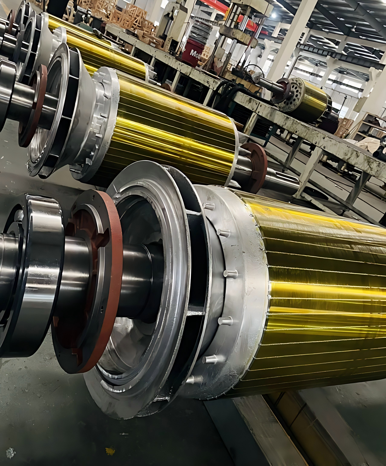
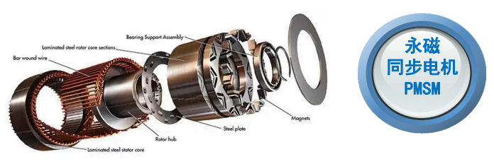
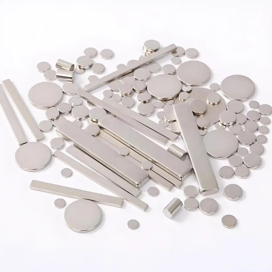
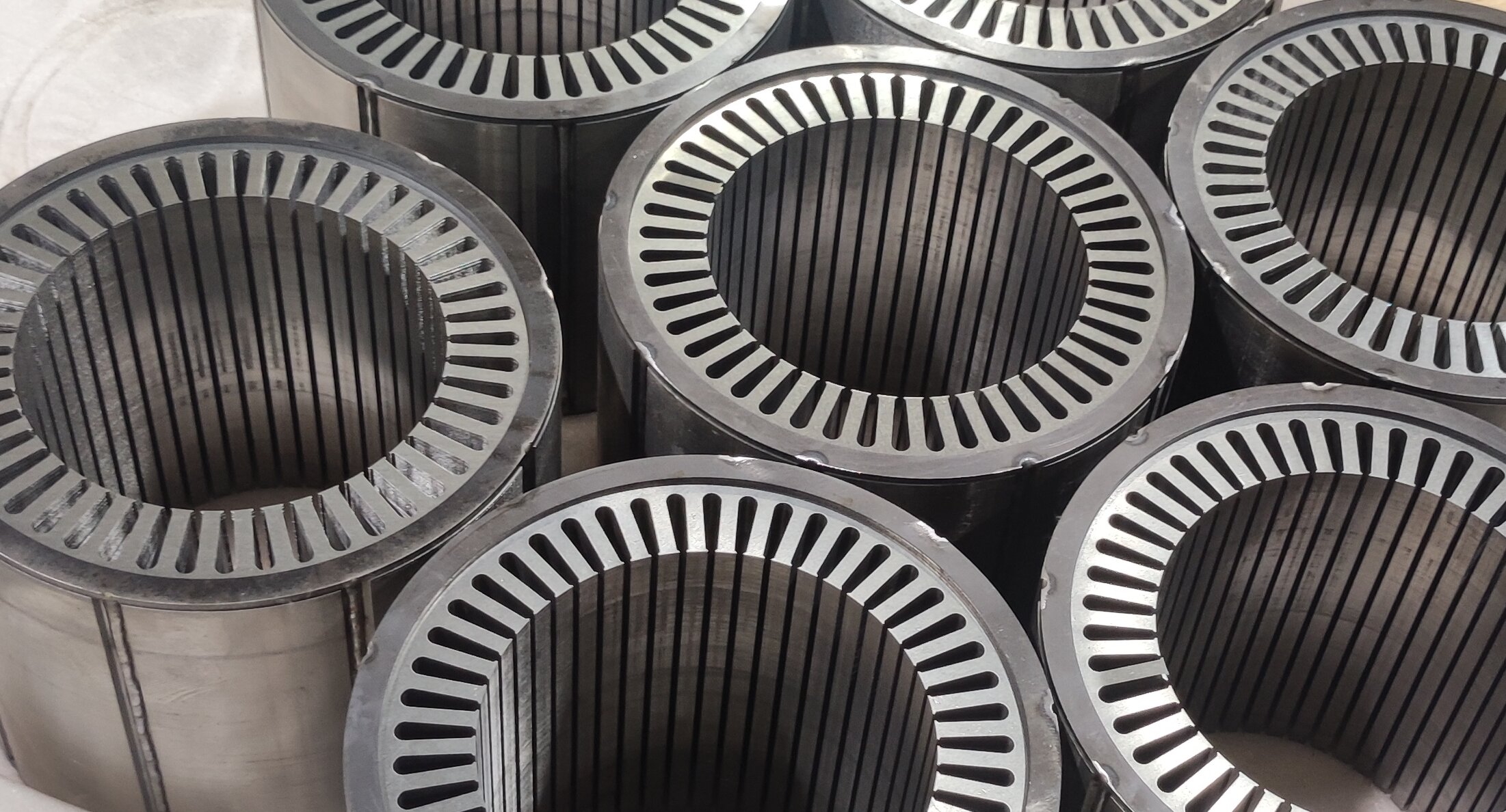
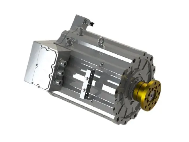
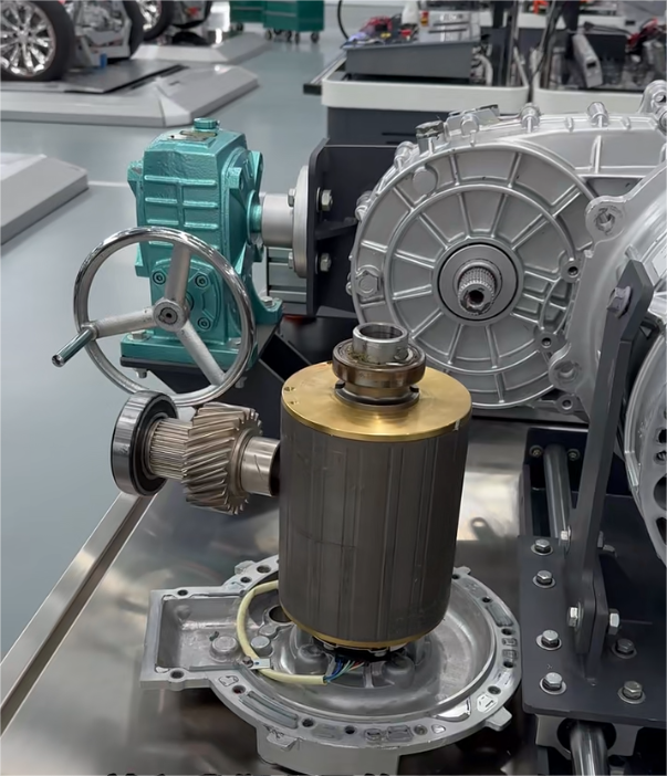
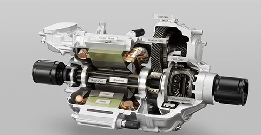
Illustration of a high-speed motor rotor structure, showing the double-layer U-shaped magnets and segmented design.
Challenge 4: High-Speed Dynamic Balancing, Residual Unbalance Suppressed to Within 50mg
At 30,000 rpm, a tiny unbalance generates hundreds of kilograms of centrifugal force. PUMBAAEV compressed the residual unbalance from the typical industry level of ≤150 mg to ≤50 mg, a reduction of 67%.
Dynamic Balancing Process Chain: Rough machining → Hot-fitting of magnets → Initial balancing → Precision machining → High-speed, full-speed-range dynamic balance verification (tested at 30,500 rpm). Unbalance correction is achieved via milling weight-removal holes in end covers, with a resolution of ±1 mg. A secondary verification after thermal shock cycles ensures post-assembly stability.
Challenge 5: Critical Speed Design, 15% Safety Margin
Vibration amplifies drastically when the operating speed approaches the rotor's first bending critical speed. PUMBAAEV designed the first bending critical speed to be 35,000 rpm, approximately 15% above the maximum rated operating speed, providing a sufficient safety margin.
Implementation Path: Increasing the bearing support span and pre-load to enhance shaft bending stiffness; concurrently using silicon nitride (Si₃N₄) ceramic bearings to maintain bearing stiffness at higher DN values (speed × bore diameter) while providing natural insulation against shaft current corrosion.
3 Stator and Thermal Management: A Coordinated Attack on High-Frequency Losses
At 30,000 rpm, the electrical frequency reaches 500 Hz. The skin effect in traditional windings causes AC copper losses to surge, necessitating a combined solution of hairpin windings and direct oil cooling.
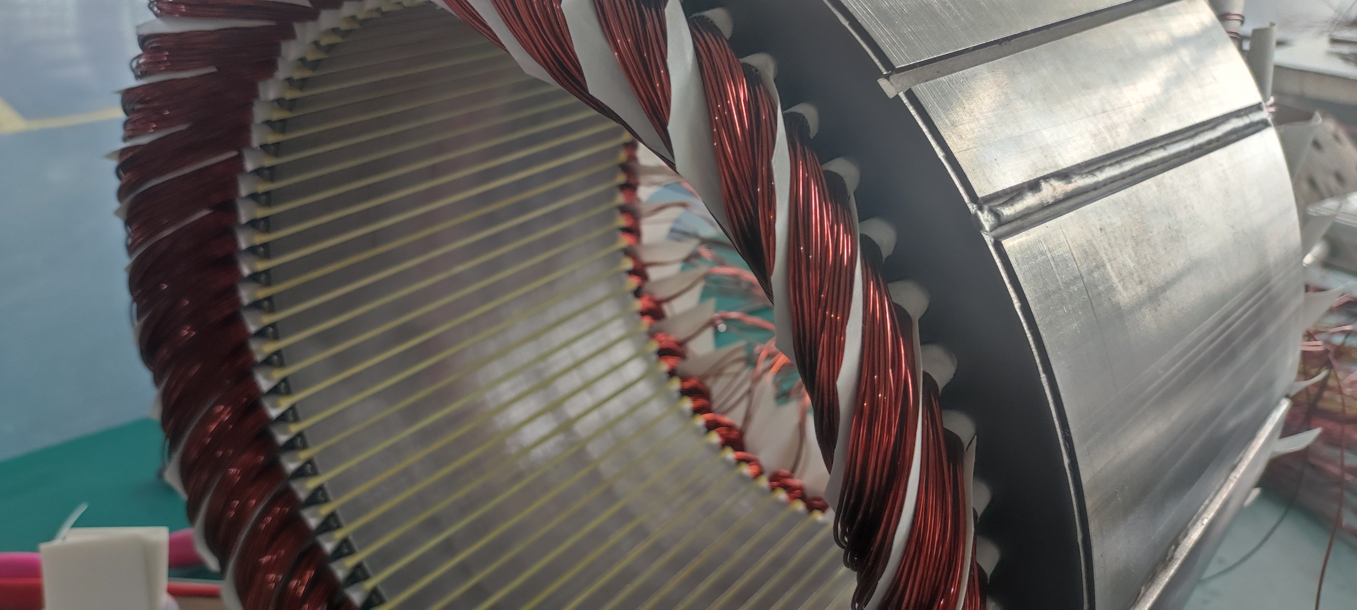
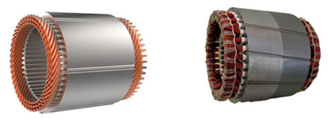
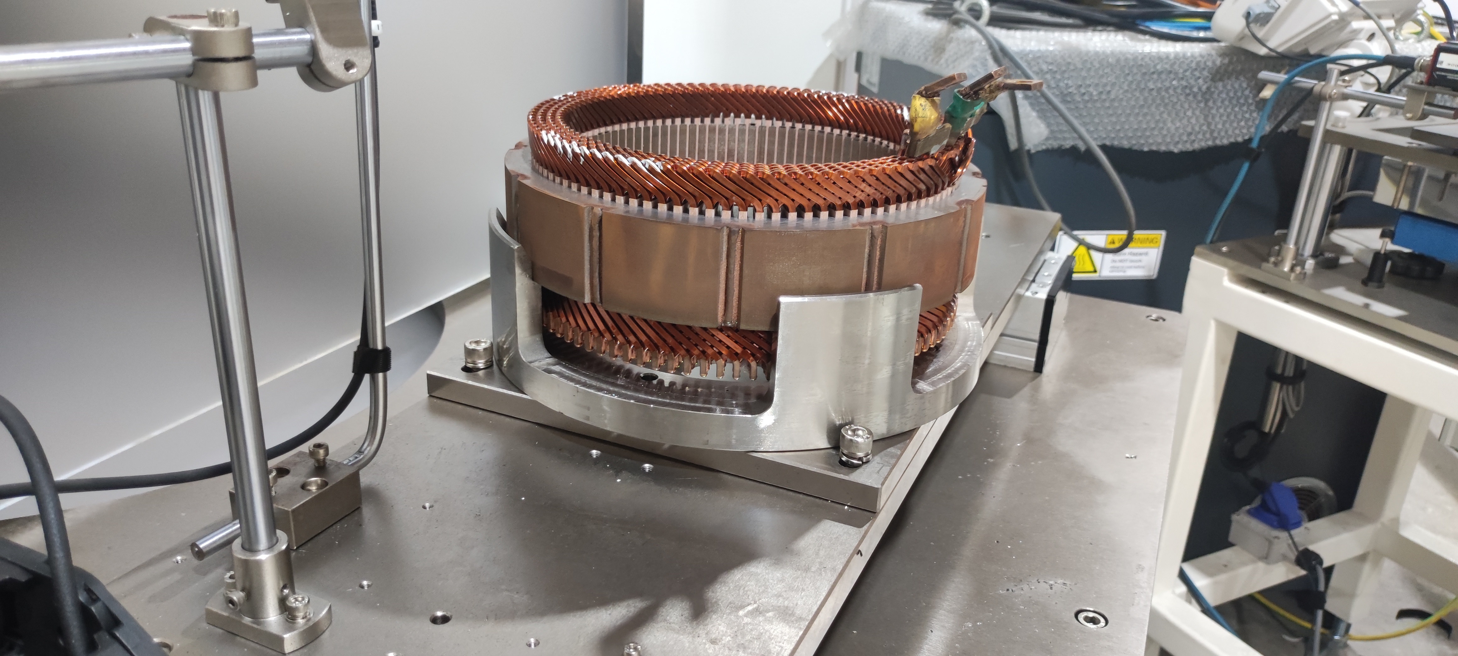
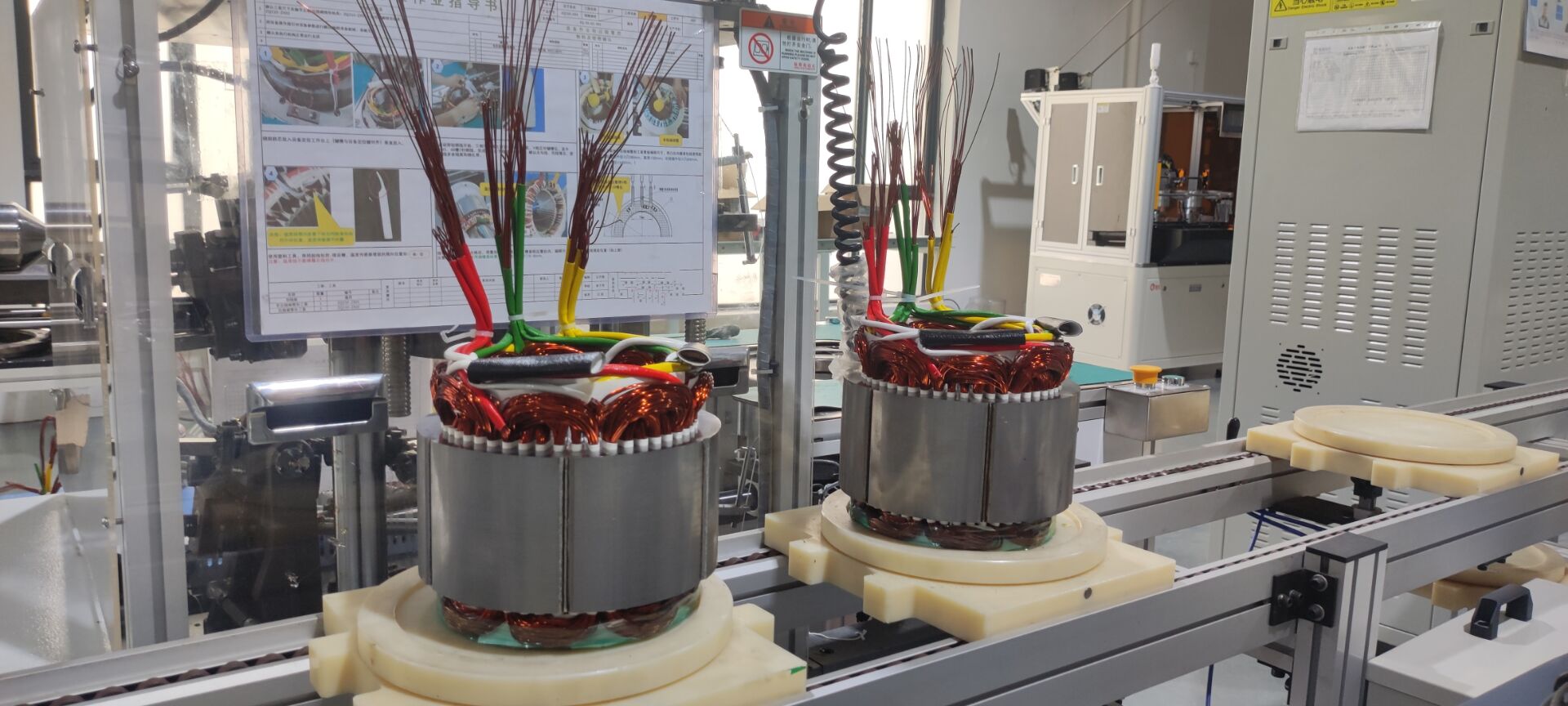
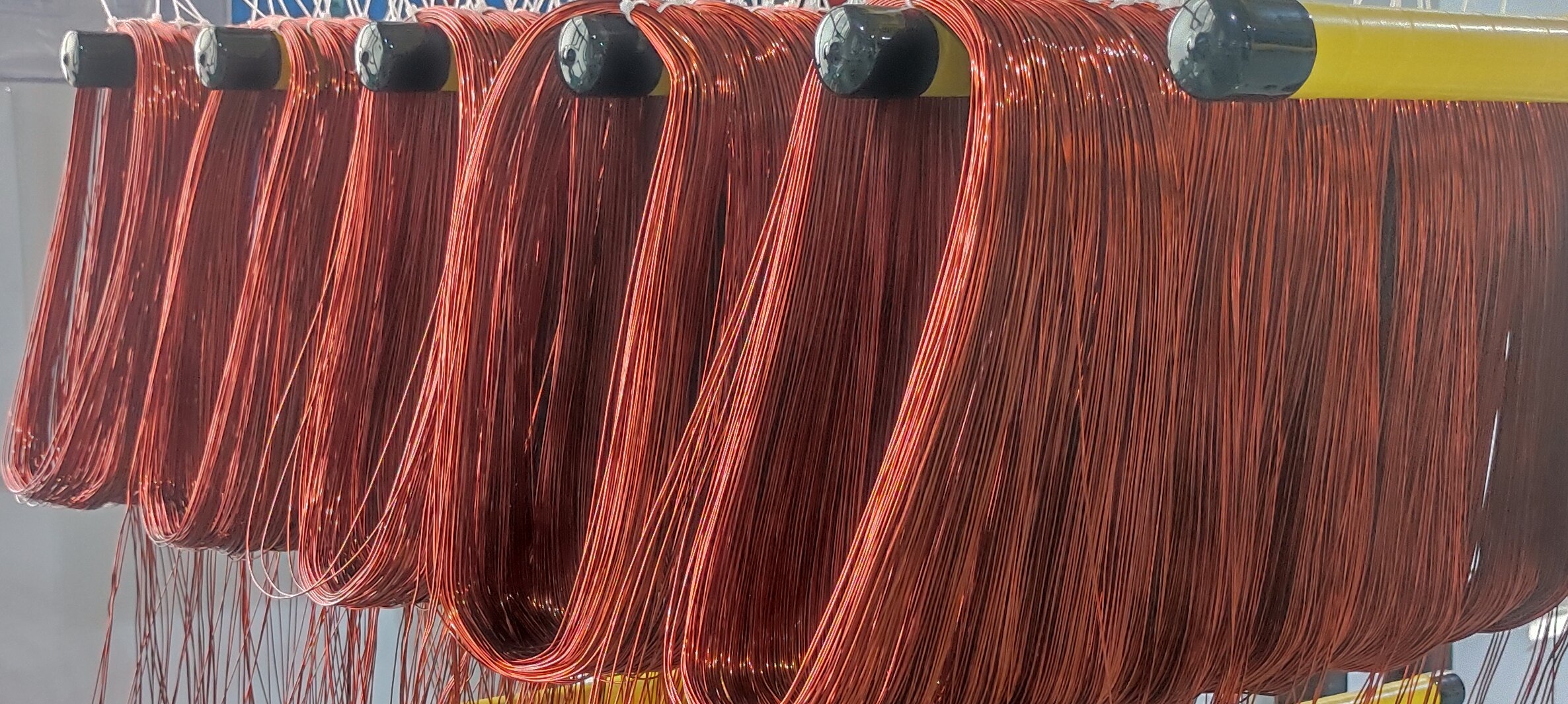
Hairpin Windings: 10-Layer Unequal-Pitch Design Optimizes AC/DC Copper Loss Ratio
The copper fill factor of rectangular cross-section flat wires can exceed 60%, far superior to round wires' 40-45%. PUMBAAEV's super motor stator uses a 10-layer unequal-pitch hairpin winding, with differentiated thicknesses for the copper strips in each layer.
-
Outer layers are thinner: Near the slot opening, they preferentially carry the high-frequency current components.
-
Inner layers are thicker: Near the slot bottom, they primarily carry the DC component.
This design controls the AC/DC copper loss ratio to about 1.15 (industry typical is 1.3-1.5), while the unequal interlayer gaps optimize the flow cross-section for cooling oil.
Core Material: Ultra-Thin Laminations Drastically Reduce High-Frequency Iron Losses
Core losses increase with frequency. At 500 Hz, losses in traditional 0.35 mm silicon steel surge. PUMBAAEV uses ultra-thin, high-frequency electrical steel with a thickness of ≤0.2 mm, reducing core losses at 500 Hz by 40-50% compared to 0.35 mm steel. The thinner laminations also increase the surface area for heat dissipation per unit volume.
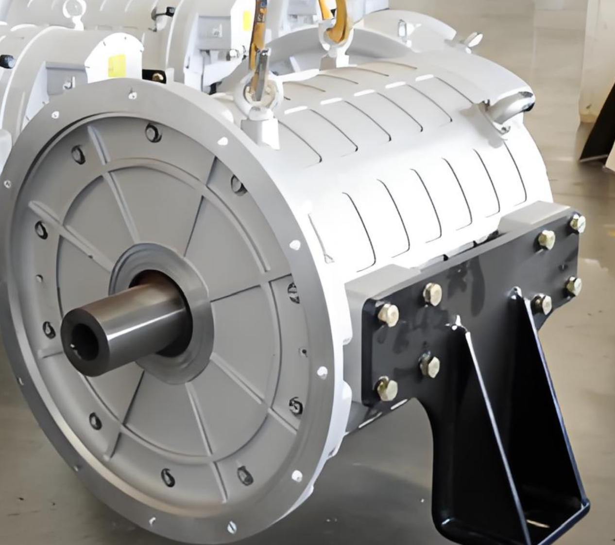
Cooling System: Direct Oil Cooling Enables Efficient Thermal Management
The stator's thermal density at 30,000 rpm is extremely high, beyond the capability of traditional jacket cooling. PUMBAAEV integrates the cooling oil passage inside the stator slots, allowing oil to flow between the windings, achieving direct contact cooling with the copper windings.
Three-Pronged Thermal Synergy:
-
Ultra-thin laminations: Reduce iron losses and increase surface area.
-
Unequal-pitch hairpins: Optimize cooling oil flow channels.
-
Direct oil cooling: Provides direct contact cooling. Measurements show steady-state winding temperature differences can be controlled within 5°C, with peak temperatures reduced by about 40°C.
4 NVH Control: The Quest for Silence in the Electric Era
With lower background noise in EVs, motor noise becomes more perceptible. The 500 Hz fundamental frequency at 30,000 rpm and its harmonics fall within the most sensitive range of human hearing (500-4000 Hz).
Primary Noise Excitation Sources:
-
Electromagnetic Force Harmonics: Generated by spatial harmonics of the air-gap flux density (determined by magnet shape, winding structure).
-
Inverter PWM Harmonics: Switching frequency and its multiples introduce current waveform harmonics, further exciting magnetic force harmonics.
-
Mechanical Unbalance: Rotor residual unbalance generates 1X rotational frequency (500 Hz) excitation, which must be separated from bearing and housing resonance frequencies.
Triple NVH Control Strategy:
-
Electromagnetic Optimization: Multi-objective optimization of slot shape, skew angle, etc., to minimize the amplitude of electromagnetic force harmonics (e.g., 6N orders). High-precision helical stacking is used for skewing.
-
Structural Reinforcement & Isolation: Enhance overall e-drive unit stiffness (housing ribs) to shift resonance frequencies away from operational bands; use high-efficiency vibration isolation bushings at mount points to reduce vibration transfer via structural paths.
-
High-Precision Dynamic Balancing: Residual unbalance ≤50 mg ensures vibration acceleration at the 1X (500 Hz) excitation is <0.1 g, with lifecycle variation control.
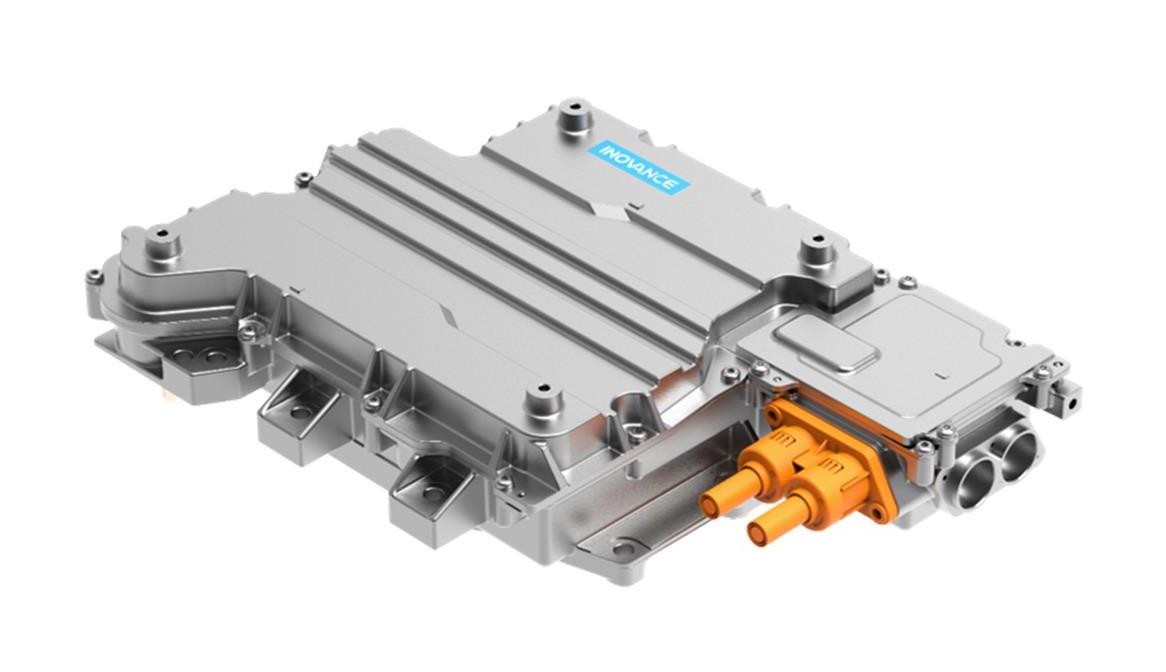
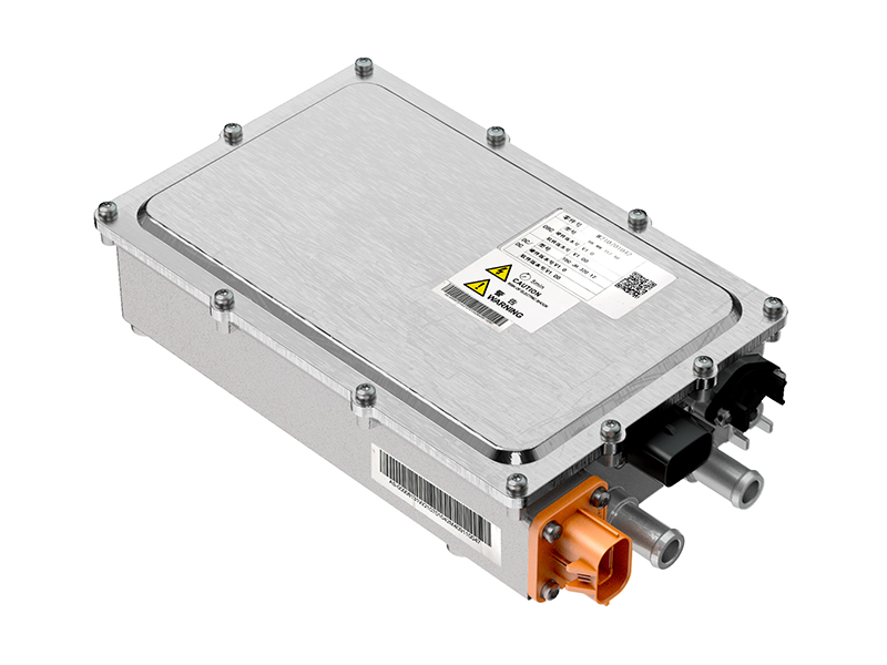
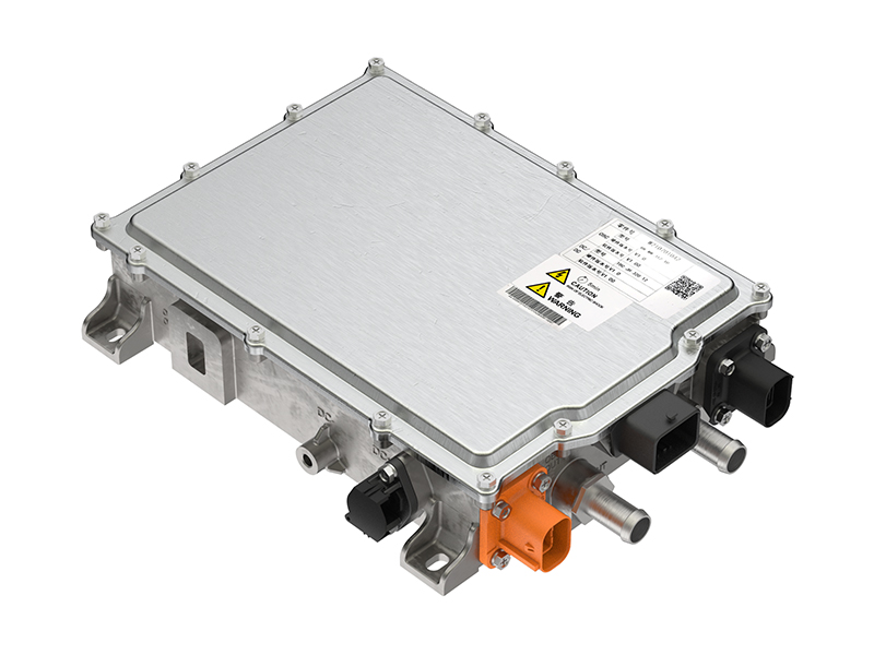
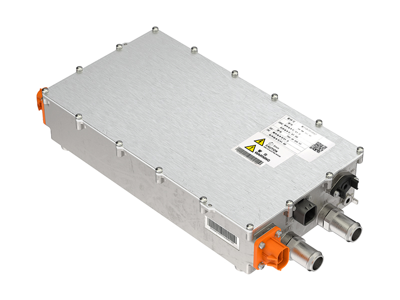
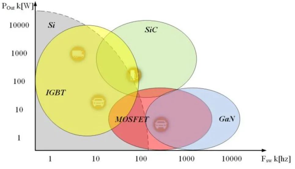
5 Control & Power Electronics: The Pivotal Role of SiC Chips
High frequency and high efficiency are inherent requirements for high-speed motors, directly dependent on advances in control and power devices.
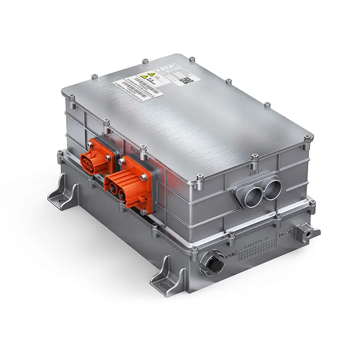
The in-house developed 1500V SiC chip is a core breakthrough. Compared to traditional IGBTs, SiC MOSFETs enable:
-
Higher Switching Frequency: Supports higher motor speeds (electrical frequencies).
-
Lower Switching Losses: Improves system efficiency, especially in the high-speed region.
-
Higher Voltage Rating: The 1500V rating provides safety margin for 800V platforms and future developments.
Control algorithms must be deeply matched with the motor, ensuring stable operation in the high-speed field-weakening region and optimal efficiency.
6 Challenges and Future Evolution
Existing Technological Bottlenecks
-
Material Cost: High-strength electrical steel and specialty coatings remain 20-30% more expensive than conventional solutions.
-
Silicon Steel Limit: Thinner laminations reduce iron loss but compromise stiffness; the iron loss-stiffness trade-off is a core challenge.
-
Bearing Lifetime Reliability: The full lifecycle reliability of high-speed ceramic bearings at ultra-high DN values requires more road test data.
-
SiC Supply Chain: Yield rates and cost for the in-house SiC chips, particularly the 4H-SiC substrate, are key industrialization hurdles.
Future Technology Pathways
-
New Materials: Amorphous/Nanocrystalline soft magnetic materials offer ~60% lower core loss than silicon steel and are a prime candidate for next-generation stator cores, though challenges remain in brittle material processing.
-
New Topologies: Axial Flux Motors (AFM), with their disc-shaped structure naturally suited for high speed, are in the roadmap of some OEMs, offering 20-40% higher theoretical power density than radial flux motors.
-
Integrated Thermal Management: Sharing cooling oil between the stator and inverter power modules can reduce thermal resistance by ~30% and simplify system architecture.
-
AI-Driven Design Revolution: Multi-physics co-simulation (electromagnetic-thermal-structural-NVH) coupled with AI/optimization algorithms holds the potential to compress high-speed motor development cycles from 24 months to under 12 months.
The boundary of technology is always beyond the next iteration. The mass production of 30,000 rpm motors marks the opening of a new technological cycle driven by systems engineering methodology, deep vertical integration, and extreme engineering thinking.